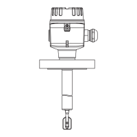
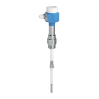
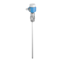
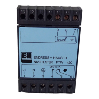
Electrical connection Liquiphant FTL31
20 Endress+Hauser
When both outputs are connected, the MIN and MAX outputs assume opposite states (XOR)
when the device is operating fault-free. In the event of an alarm condition or a line break,
both outputs are de-energized.
Connection for function monitoring using XOR operation Yellow LED (ye) LED red (rd)
Sensor covered
Max output
Min output
Sensor not covered
Max output
Min output
Fault
Wire colors for M12 plug:
• 1 = BN (brown)
• 2 = WT (white)
• 3 = BU (blue)
• 4 = BK (black)
Symbols
K1/K2
Description
LED lit
LED not lit
Fault or warning
External load
Connection with valve plug
Depending on the assignment of the connector or the wiring of the cable, the device works in
either the MAX or MIN operating mode.

 Loading...


