3 Installation OxyMax W COS 41
10 Endress+Hauser
To aid installation in strongly fluctuating water levels, e.g. in rivers or lakes, there is a
floating body COA 110-50 available (Fig. 3.10).
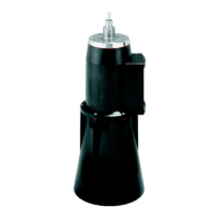
Flow operation
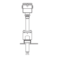
The COA 250-A flow assembly (Fig. 3.11) with automatic self-venting is suitable for use
in pipelines or hose connections. The inlet is at the bottom of the assembly, the outlet at
the top (connection thread G ¾). It can be installed in a pipe by using two 90° pipe
brackets to allow inflow to the assembly (Fig. 3.12, Pos. 6).
1
2
3
4
5
6
7
Cable route with strain relief and rain
protection
Mounting ring for ropes and chains
with locking screw
Lugs Ø 15; 3x120° for anchoring
Saltwater-resistant plastic float
Pipe 40x1, rust- proof steel SS 316Ti
Shock absorb er and weig ht
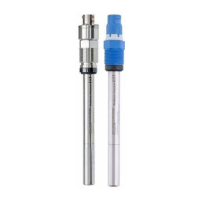
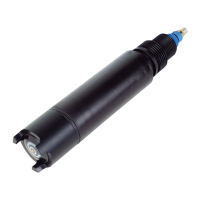
Oxygen sens or COS 41
Fig. 3.10: Float COA 110-50
Fig. 3.11: Flow assembly COA 250-A Fig. 3.12: Bypass installation with manually
actuated valves or solenoid valves
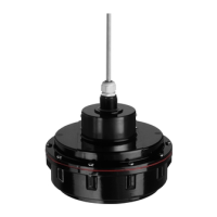
1 Screw-in part for sensor 1 Main line
2 Screw ring 2 Medium return
3 Meter body 3 COS 41
4 Connection thread G ¾ 4, 7 Manually actuated or solenoid valves
5 Dummy plug on the connection 5 Flow assembly COA 250-A
thread for spray head CO R 3 6 90° pipe bracket
8 Medium removal
800
500
220
Ø200
1
2
3
4
5
6
7
G1
C07-COS41xxx-11-05-00-xx-007.EPS
-COS41xxx-11-05-00-xx-008.EPS
100
90
Ø34
23
90
G ¾
68
196
G¾
Ø34
1
2
3
4
1
23
4
6
7
8
C07-COS41xxx-11-05-00-xx-009.EPS
5
 Loading...