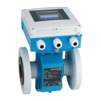
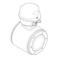
Proline Promag W 400 EtherNet/IP Installation
Endress+Hauser 25
2. To ensure compliance with device specifications, install the measuring device
between the pipe flanges in a way that it is centered in the measurement section.
3. If using ground disks, comply with the Installation Instructions provided.
4. Observe required screw tightening torques → 25.
5. Install the measuring device or turn the transmitter housing so that the cable entries
do not point upwards.
A0013964
Mounting the seals
L
CAUTION
An electrically conductive layer could form on the inside of the measuring tube!
Risk of measuring signal short circuit.
‣
Do not use electrically conductive sealing compounds such as graphite.
Comply with the following instructions when installing seals:
• Make sure that the seals do not protrude into the piping cross-section.
• For DIN flanges: only use seals according to DIN EN 1514-1.
• For "hard rubber" lining: additional seals are always required.
• For "polyurethane" lining: generally additional seals are not required.
Mounting the ground cable/ground disks
Comply with the information on potential equalization and detailed mounting instructions
for the use of ground cables/ground disks → 44.
Screw tightening torques
Please note the following:
• The screw tightening torques listed below apply only to lubricated threads and to pipes
not subjected to tensile stress.
• Tighten the screws uniformly and in diagonally opposite sequence.
• Overtightening the screws will deform the sealing faces or damage the seals.
Screw tightening torques for EN 1092-1 (DIN 2501), PN 6/10/16/25/40
Nominal diameter Pressure rating Threaded fasteners Max. screw tightening torque [Nm]
[mm] [bar] [mm] Hard rubber Polyurethane
25 PN 40 4 × M12 – 15
32 PN 40 4 × M16 – 24
40 PN 40 4 × M16 – 31
50 PN 40 4 × M16 48 40
65
1)
PN 16 8 × M16 32 27
65 PN 40 8 × M16 32 27
80 PN 16 8 × M16 40 34
80 PN 40 8 × M16 40 34
100 PN 16 8 × M16 43 36
100 PN 40 8 × M20 59 50

 Loading...


