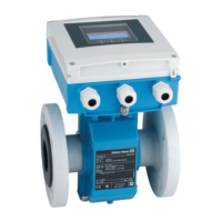
Proline Promag W 400 EtherNet/IP System integration
Endress+Hauser 73
Name Description Byte
10. Totalizer 2 37 to 40
11. Totalizer 3 41 to 44
1) Structure: Code, number, description (e.g.: 16777265 F882 input signal)
Detailed description
• Diagnostic information → 114
• Information events → 118
Configurable input group
Input Assembly Configurable (Assem101) 88 byte
Name Description Format
Input Assembly Configurable 1. - 10. Input values 1 to 10 Real
11. - 20. Input values 11 to 20 Double integer
Possible input values
Possible input values 1 to 10:
• Off
• Mass flow
• Volume flow
• Corrected volume flow
• Target mass flow
• Carrier mass flow
• Density
• Reference density
• Concentration
• Temperature
• Carrier pipe temperature
• Electronics temperature
• Oscillation frequency 0
• Oscillation frequency 1
• Oscillation amplitude 0
• Oscillation amplitude 1
• Oscillation frequency 0
• Oscillation frequency 1
• Oscillation damping 0
• Oscillation damping 1
• Signal shift
• Tube damping fluctuation 0
• Tube damping fluctuation 1
• Exciter current 0
• Exciter current 1
• Monitoring of exciter current 0
• Monitoring of exciter current 1
• Totalizer 1
• Totalizer 2
• Totalizer 3
• Sensor integrity
Possible input values 11 to 20:
• Off
• Current diagnosis
• Previous diagnosis
• Mass flow unit
• Volume flow unit
• Corrected volume flow unit
• Temperature unit
• Density unit
• Reference density unit
• Concentration unit
• Current unit
• Status verification
• Totalizer 1 unit
• Totalizer 2 unit
• Totalizer 3 unit
• Verification result
Permanently assigned output group
Output Assembly Fix (Assem102) 64 byte
Name Description (format) Byte Bit Value
Output
Assembly Fix
1. Totalizer 1 1 1
• 0: Enable
• 1: Disable
2. Totalizer 2 2
3. Totalizer 3 3
4. Pressure compensation 4
5. Reference density compensation 5
6. Temperature compensation 6
7. Verification 7

 Loading...


