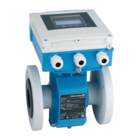
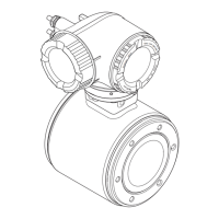
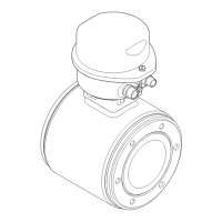
Proline Promag W 800 Electrical connection
Endress+Hauser 49
7.2.6 Requirements for the supply unit
Supply voltage
Order code
"Power supply"
Terminal numbers Terminal voltage Frequency range
Option K
Option S
(wide range power unit)
1 (L+/L), 2 (L-/N)
DC 24 V –20 to +25 % –
AC 100 to 240 V –15 to +10 % 50/60 Hz, ±3 Hz
7.2.7 Preparing the measuring device
Carry out the steps in the following order:
1. Mount the sensor and transmitter.
2. Sensor connection housing: Connect connecting cable.
3. Transmitter: Connect connecting cable.
4. Transmitter: Connect signal cable and cable for supply voltage.
NOTICE
Insufficient sealing of the housing!
Operational reliability of the measuring device could be compromised.
‣
Use suitable cable glands corresponding to the degree of protection.
1. Remove dummy plug if present.
2. If the measuring device is supplied without cable glands:
Provide suitable cable gland for corresponding connecting cable.
3. If the measuring device is supplied with cable glands:
Observe requirements for connecting cables → 44.
7.2.8 Preparing the connecting cable for the remote version
When terminating the connecting cable, pay attention to the following points:
1. In the case of the electrode cable:
Make sure that the ferrules do not touch the core shields on the sensor side.
Minimum distance = 1 mm (exception: green “GND” cable)
2. In the case of the coil current cable:
Insulate one core of the three-core cable at the level of the core reinforcement. You
only require two cores for the connection.
3. For cables with fine-wire cores (stranded cables):
Fit the cores with ferrules.

 Loading...


