Installation Proline Promass I 100 Modbus RS485
22 Endress+Hauser
Zero point adjustment
All measuring devices are calibrated in accordance with state-of-the-art technology. The
zero point obtained in this way is printed on the nameplate of the measuring device.
Calibration takes place under reference conditions ( 81). Therefore, a zero point
adjustment in the field is generally not required! )
Experience shows that zero point adjustment is advisable only in special cases:
• To achieve maximum measuring accuracy even with very low flow rates
• Under extreme process or operating conditions, e.g.:
– high process temperature (> 50 °C (122 °F)
– high viscosity (> 100 cSt)
– high process pressure (> 20 bar (290 psi))
6.2 Mounting the measuring device
6.2.1 Required tools
For sensor
For flanges and other process connections: Corresponding mounting tools
6.2.2 Preparing the measuring device
1. Remove all remaining transport packaging.
2. Remove any protective covers or protective caps present from the sensor.
3. Remove stick-on label on the electronics compartment cover.
6.2.3 Mounting the measuring device
WARNING
Danger due to improper process sealing!
‣
Ensure that the inside diameters of the gaskets are greater than or equal to that of the
process connections and piping.
‣
Ensure that the gaskets are clean and undamaged.
‣
Install the gaskets correctly.
1. Ensure that the direction of the arrow on the nameplate of the sensor matches the
flow direction of the fluid.
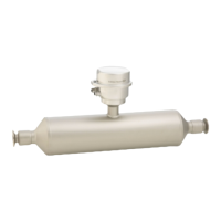
2. Install the measuring device or turn the transmitter housing so that the cable entries
do not point upwards.
A0013964
 Loading...

