Installation Proline Prowirl R 200 HART
24 Endress+Hauser
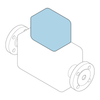
The following dimensions must be observed to guarantee problem-free access to the device
for service purposes:
• A =100 mm (3.94 in)
• L = L + 150 mm (5.91 in)
Inlet and outlet runs
To attain the specified level of accuracy of the measuring device, the inlet and outlet runs
mentioned below must be maintained at the very minimum.
1
15 DN×
5 × DN
3
25 × DN
5 × DN
40 × DN
5 × DN
4
2
20 × DN
5 × DN
5
20 × DN
5 × DN
6
17 × DN + 8 × h
5 × DN
h
7
50 × DN
5 × DN
9
40 × DN
5 × DN
8
5 × DN
DN 25 (1"):≤
DN 40 (1½"):≥
A0019189
8 Minimum inlet and outlet runs with various flow obstructions
h Difference in expansion
1 Reduction by one nominal diameter size
2 Single elbow (90° elbow)
3 Double elbow (2 × 90° elbows, opposite)
4 Double elbow 3D (2 × 90° elbows, opposite, not on one plane)
5 T-piece
6 Expansion
7 Control valve
8 Two measuring devices in a row where DN ≤ 25 (1"): directly flange on flange
9 Two measuring devices in a row where DN ≥ 40 (1½"): for spacing, see graphic
• If there are several flow disturbances present, the longest specified inlet run must
be maintained.
• If the required inlet runs cannot be observed, it is possible to install a specially
designed flow conditioner → 24.
Flow conditioner
If the inlet runs cannot be observed, the use of a flow conditioner is recommended.

 Loading...