Proline Prowirl R 200 HART Installation
Endress+Hauser 25
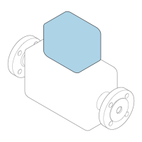
The flow conditioner is fitted between two pipe flanges and centered by the mounting
bolts. Generally this reduces the inlet run needed to 10 × DN with full accuracy.
A0019208
1 Flow conditioner
The pressure loss for flow conditioners is calculated as follows: ∆ p [mbar] = 0.0085 ⋅ ρ
[kg/m
3
] ⋅ v
2
[m/s]
Example for steam Example for H
2
O condensate (80 °C)
p = 10 bar abs. ρ = 965 kg/m
3
t = 240 °C → ρ = 4.39 kg/m
3
v = 2.5 m/s
v = 40 m/s ∆ p = 0.0085 ⋅ 965 ⋅ 2.5
2
= 51.3 mbar
∆ p = 0.0085 ⋅ 4.394.39 ⋅ 40
2
= 59.7 mbar
ρ : density of the process medium
v: average flow velocity
abs. = absolute
For the dimensions of the flow conditioner, see the "Technical Information" document,
"Mechanical construction" section
Outlet runs when installing external devices
If installing an external device, observe the specified distance.
A0019205
PT Pressure
TT Temperature device
Installation dimensions
For the dimensions and installation lengths of the device, see the "Technical
Information" document, "Mechanical construction" section.

 Loading...