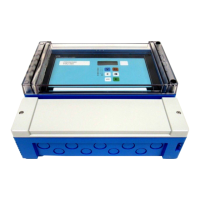
The "Relay/Controls" menu
100
Overview: Parametrization of a pump rate control
Step Parameter set or submenu Parameter Remarks see section
1 "relay/controls" submenu Select "pump control 1" or "pump control 2".
2pump control N
(N = 1 or 2)
reference Select the level according to which the pumps are controlled. 101
number of pumps Select the number of pumps.
Note: A relay must be available for each pump.
101
standby pump
1)
Define, if one of the pumps is to be a standby pump. 101
reset Restarts an existing pump control; is not used during the parametrization. 101
3pump control N
(N = 1 or 2)
function Select "limit parallel" or "limit simple". 102
load control Select the type of load control (only relevant for alternating pump control) 102
4pump control N
(N = 1 or 2)
switch on point Define the switch on point. 109
switch off point Define the switch off point. 109
min. pumprate/min Define the minimum pump rate. 109
crust reduction Define the inaccuracy for the switching points (to reduce crust formation). 109
switch on border Define the switch on border. 110
hook up interval Define the hook-up interval. 110
alternate Select if an alternating pump control is to be performed. 110
5pump control N
(N = 1 or 2)
Select a pump.
(The following parameters must be configured for each pump individually.)
6pumpe M control N
(M = 1 - 6)
(N = 1 or 2)
switch on delay Define the switch on delay. 103
degree of use Define the desired degree of use (percentage) for this pump;
(only relevant for alternating pump control)
104
max. use time Define the maximum use time for this pump
(only relevant for alternating pump control with "load control" =
"starts+time")
104
7 pump M control N
(M = 1 - 6)
(N = 1 or 2)
backlash interval Define the backlash interval. 105
backlash time Define the backlash time. 105
error handling Define the error handling. 105
8 pump M control N
(M = 1 - 6)
(N = 1 or 2)
pump feedback Select the digital input used for pump feedback. 106
feedback delay Define the time interval in which a feedback is required. 106
feedback meaning Define the meaning of the pump feedback. 106
9 relay allocation Allocate a relay to the pump.
Note: By default, relay 1 is configured as alarm relay.
10 relay N
(N = 1 - 6)
function Select "pump M/control N". 108
invert Select if the switching signal is inverted (default: no). 108
11 pump control N Select the next pump and continue with step 6 until all pumps have been
configured.
If all pumps are configured: Press to return to the "relay/controls" menu.
1) only for instruments with external limit switches; the stand-by pump always is the last of the M pumps.

 Loading...


