Prothermo NMT81 Installation
Endress+Hauser 21
96.9 (3.81)
Ø100.9
(3.97)
1
400 ± 10 (15.75 ± 0.39)
147 (5.79)
A0042793
9 Adjustable flange. Unit of measurement mm (in)
1 Flange (JIS, ASME, JPI, DIN)
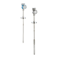
5.7 Element No. 1 position
Element No. 1 is mounted inside the probe according to the combinations of order
specifications as described in the figure below. The element No. 1 is usually the element
mounted in the the lowest position in the tank.
When selecting 085 = E (customized positioning) the element No. 1 can be positioned in a
range from: 100 mm (3.94 in) (d) measured from end of the probe up to probe length
-315 mm (12.40 in) (d)
When selecting 085 = F, the element No. 1 is mounted at the position of
100 mm (3.94 in)from the bottom of the probe (b in the figure), and the element at the
highest point is mounted at a position 315 mm (12.40 in) (d in the figure) from the bottom of
the flange. All other elements are mounted at a spacing determined by following formula.
Element spacing = (a - b - d ) / (number of measuring points - 1)
 Loading...

