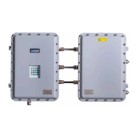
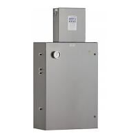
Operating Instructions SS2100i-2 TDLAS Gas Analyzer
36 Endress+Hauser
Miniature Fuse, 5 x 20 mm, Time Delay
Miniature Fuse, 5 x 20 mm, Time Delay
Miniature Fuse, 5 x 20 mm, Time Delay
Miniature Fuse, 5 x 20 mm, Time Delay
Miniature Fuse, 5 x 20 mm, Time Delay
Fuse specifications for 240 VAC systems
Miniature Fuse, 5 x 20 mm, Time Delay
Miniature Fuse, 5 x 20 mm, Time Delay
Miniature Fuse, 5 x 20 mm, Time Delay
Miniature Fuse, 5 x 20 mm, Time Delay
Miniature Fuse, 5 x 20 mm, Time Delay
Fuse specifications for 120 VAC systems
4.14.1 To connect electrical power to the analyzer
1. Open the analyzer enclosure cover according to the procedure under To open an analyzer enclosure cover → to
gain access to the field interface terminal block.
2. Install an appropriate compound barrier seal type gland into the M20 access port on the bottom left of the
electronics enclosure. Refer to Application of gland lubricant → .
3. Run cable from the power distribution panel to the gland.
An approved switch or circuit breaker rated for 15 amps should be used and clearly marked as the
disconnecting device for the analyzer.
Because the breaker in the power distribution panel or switch will be the primary means of disconnecting the
power from the analyzer, the power distribution panel or switch should be in close proximity to the
equipment and within easy reach of the operator.
4. Pull ground, neutral, and hot wires (#14 AWG minimum) into the analyzer enclosure.
5. Strip back the jacket and/or insulation of the wires just enough to connect to the power terminal blocks (X1).
6. Attach the neutral and hot wires to the power terminal blocks by connecting the neutral wire to terminal X1-2,
the hot wire to terminal X1-1, as shown in Fig 22 → .
7. Connect the ground wire to the ground bus bar marked .
Failure to properly ground the analyzer may create a high-voltage shock hazard.
8. Verify that each connection is secure.
9. Close the analyzer enclosure cover.
4.15 Connecting the gas lines
Once you have verified that the analyzer is properly wired, you are ready to connect the sample supply and sample
return lines. All work should be performed by technicians qualified in pneumatic tubing.
Using electro-plated coated ¼ in O.D x 0.35 in wall thickness, seamless stainless steel tubing is recommended. The
SS2100 for trace analytes utilize SilcoTek SN2000 coated tubing. SN2000-coated tubes may be used for the sample
Housed in fuse terminal blocks. Illuminated LED indicates blown fuse. Refer to Fig 7. Components in SS2100i-2 electronics enclosure

 Loading...


