US Patents 7,922,100; 7,737,762
Auxiliary Switch Installation Page 2 AW000745-C
Dual transformer installation with or without a common wire
The Auxiliary Switch facilitates the installation of a thermostat
in a dual transformer HVAC system, regardless of whether a
common wire connection from the equipment to the
thermostat is available.
The dual transformer instructions on this page should be
used with installations incorporating separate Heating and
Cooling equipment, each with its own transformer. For a Heat-
only HVAC installation or an integrated Heat/Cool installation
that uses a single transformer to service both Heat and Cool
parts of the equipment, please refer to the instructions on
Page 1.
The Auxiliary Switch is installed on or close to the equipment
so that the five wire cable reaches the control terminals inside.
The Auxiliary Switch should not be installed inside the
HVAC equipment enclosure (doing so may void the HVAC UL
certification).
Before Starting the Installation:
Check that the package includes 1 Auxiliary Switch Unit, 1
signal coupler and 5 Splice Wire Caps.
Turn off the power to the furnace, air conditioning and/or
heat pump, either at the shut off switch, or at the
electrical panel.
Thermostat site:
Step 1 - Remove the old thermostat from the backplate. If
there is no backplate, then remove the thermostat from the
wall to access the wiring. Next, label the wires according to
which terminal block they connect to (R,Y,W,G). Now
disconnect the wires and remove the existing backplate.
Step 2 – Mount the new backplate and connect the wire
labelled RC to the R terminal block.
Step 3 – Install the signal coupler provided with the Auxiliary
Switch between W and C terminal blocks on the backplate.
Twist the signal couple
r wire with the wire labelled W to
ensure that it is held securely.
Connect the wire labelled W to the C terminal block. Any
remaining wires should be connected as per their installation
instructions.
Step 4 – Make note of the color and/or labels on the wires
attached to each of the terminal blocks. Attach the thermostat
to the backplate.
Equipment site:
Step 5 – In the equipment area, find a convenient location to
mount the Auxiliary Switch. With separate equipment, it is
generally advantageous to mount the Auxiliary Switch at the
Cooling equipment. The location should be outside the
equipment but close enough so that the five wire cable
reaches the thermostat connections inside. Mount the
Auxiliary Switch using 2 screws or adhesive pad provided.
Step 6 – Before disconnecting wires at the equipment, label
them according to which equipment terminal block they are
connected, verifying these labels match the labels attached in
step 1.
Step 7 – Pass the five wire cable from the Auxiliary Switch
through a convenient access hole in the equipment.
Step 8 – The wires labelled RC and W must be spliced to the
Auxiliary Switch cable and equipment as follows:
• Wire labelled RC and Auxiliary Switch YELLOW wire both
to the Cooling equipment RC terminal.
• Wire labelled W to the Auxiliary Switch WHITE wire.
Step 9 – Connect the three remaining wires from the Auxiliary
Switch to the furnace as follows:
• RED wire to the Heating equipment RH terminal.
• GREEN wire to the Heating equipment W terminal.
• BLUE wire to the Cooling equipment C terminal.
Step 10 – Restore power to the equipment and follow the
equipment configuration instructions in the thermostat user
manual for testing.
Step 11 - Record the serial number of the unit, name and
address of the owner, and make and model of the heating
and/or cooling equipment. Install the Connection Diagram
sticker (AW000785) on a visible place on the HVAC cabinet or
on the wall close to the Auxiliary Switch.
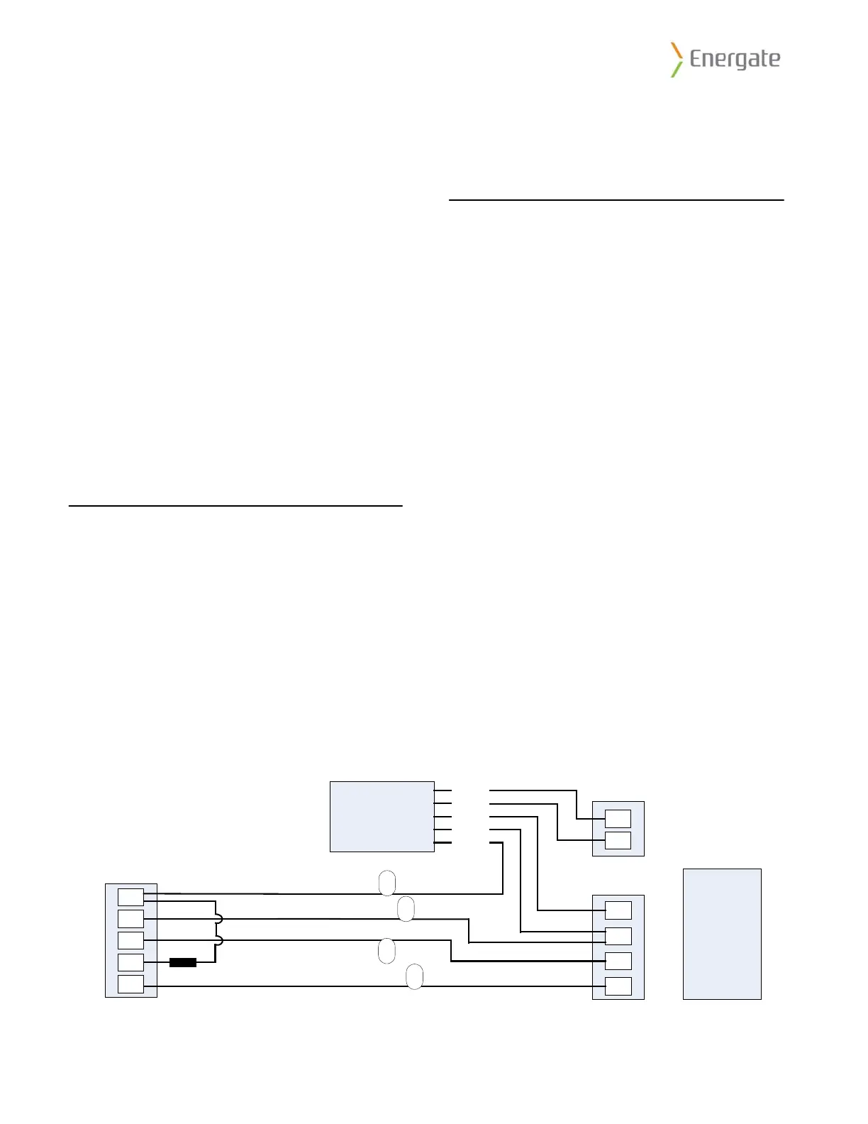
Auxiliary
Switch
Dual Transformer
Connection Schematic
WHITE
YELLOW
RED
GREEN
BLUE
R
G
W
Y
C
RC
G
Y
C
Thermostat
Cooling Equipment
RH
W
Heating Equipment
Signal Coupler
Legend
R – 24VAC
C – Common
W – Heating
Y – Cooling
G – Fan
Example for single stage
Heat/Cool system.
W
RC
G
Y
Labels per steps 1 and 6.
 Loading...