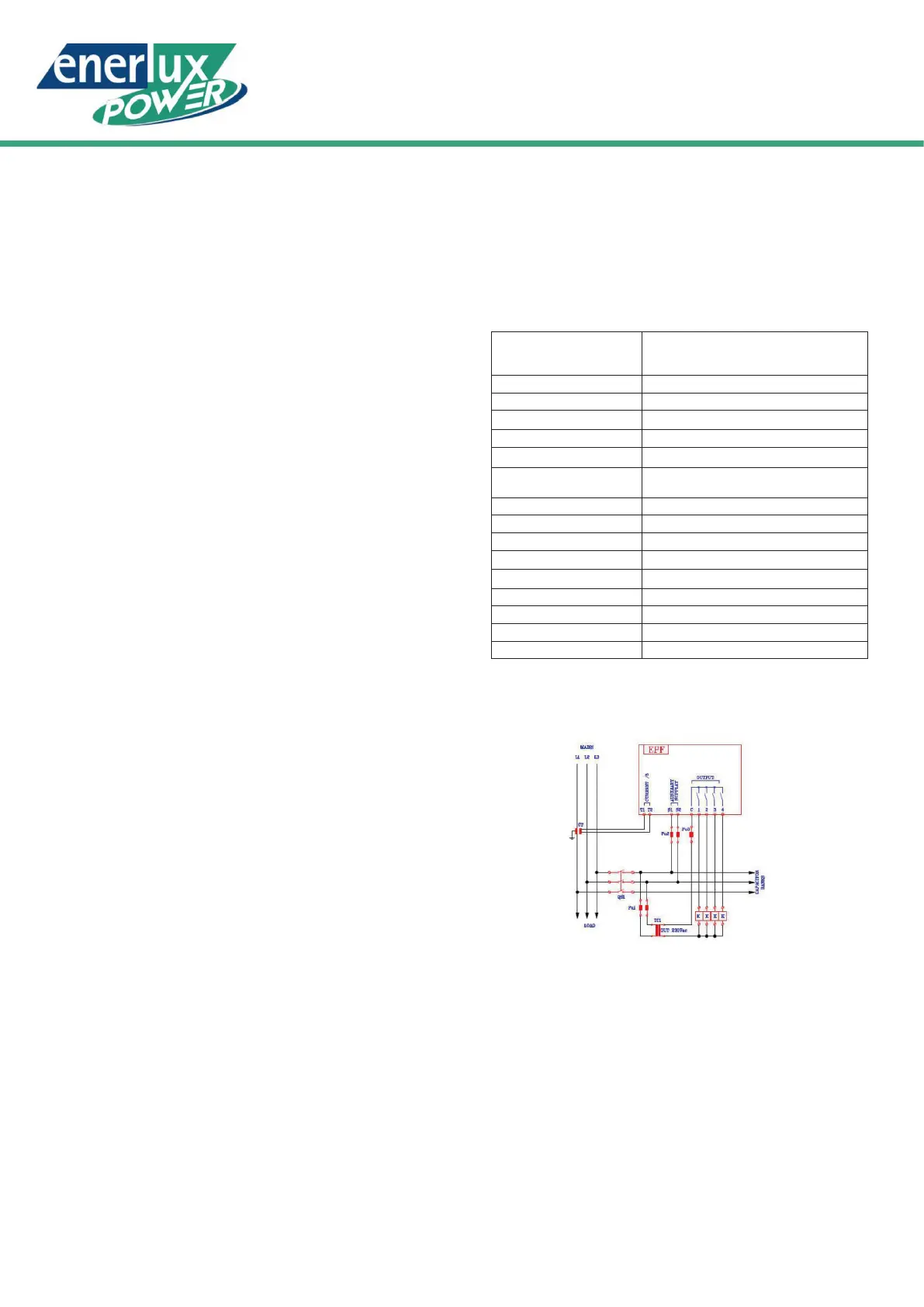
SINGLE PHASE CONNECTION:
Optional, communication and module
WARRANTY
For a continuous development of its products, ENERLUX POWER
Srl reserves the right to make changes to the technical data and the
functions without notice. The consumer is guaranteed against the
product conformity defects according to the European Directive
1999/44/c and the document on the guarantee policy of the
manufacturer.
Compliance to:
-Directive 2014/35/EU (low voltage)
-Directive 2014/30/EU (EMC)
-Directive 2011/65/CE (ROHS)
-Directive 2012/19/UE (RAEE)
Enerlux Power s.r.l.
Via G.Rossa, 6 - 46019 VIADANA (MN) Italy
Tel. + 39 0375 785887 - fax +39 0375 785877 info@enerlux.it
After 30 seconds of displaying the selected parameter, if is no
pressed any button, EPF returns to the main page view (Power
factor). To switch from automatic mode to manual mode and
vice versa, it is necessary to press the MAN/AUT button and
consequently, the corresponding signal LED lights up.
To open or close the output relays it is necessary to select the
manual mode, press the UP or DOWN button to select the output
bank indicated by the ashing led, and nally press the NAV
button to conrm your selection. In manual mode the automatic
power factor reglation function is turned off , but EPF continue to
check the measurements and alarms. The status of the output is
stored in the non volatile memory,after a power up the regulator
restore the last output status before to restart the automatic
regulation function.The same capacitor banks are inserted as
soon as the power supply is restored. In automatic mode, EPF
manages the output relays state to connect or disconnect the
capacitive loads to reach the threshold setcosφ.The algorithm
that manage the output relays state takes into account of all the
measures and other parameters like the power and the number
of operation of each step and the reconnection time.
EPF manages the following alarms:
• Setting the nominal voltage of the capacitor
(from 80 to 1000V standard pitch)
• Setting sensitivity of delayed trip
• Cosφ display between voltage and current of fundamental
• Display line voltage true RMS
• Display line current true RMS
• Display Reactive Power in excess or deficiency of the set value ( Delta Power)
• Filter anti-sway
• Management wear uniform batteries
HIGH VOLTAGE:
LOW VOLTAGE:
HIGH CURRENT:
LOW CURRENT:
UNDER COMPENS:
HIGH THD%:
OVER THD%:
OVER TEMP:
Line voltage higher than 110% of the capacitors
nominal voltage for 15 min; disconnection of
the inserted capacitor banks.
Line voltage of less than 85% of the
nominal for 5 sec; disconnection of the
inserted capacitor banks.
Current higher than 110% of the rated
current for 2 min.
Current lower than 5% of the nominal
current for 5sec (no battery insertion and
disconnection of the inserted batteries if
the alarm remains for more than 2 minutes)
Power factor lower than the cos
φ
setpoint
for more than 15 min
Higher than the HIGH THD I% threshold
for 2 min; disconnection of the inserted
capacitor banks.
THDI% higher than the OVER THD I% threshold;
disconnection of the inserted capacitor banks.
Measured temperature higher than the OVER
TEMP threshold; disconnection of the inserted
capacitor banks.
When an alarm is displayed, the LED ALM blinks with the
measure and the correspondent NAV segment.
For example, in the case of an HIGH VOLTAGE alarm, the
LED ALM and the segment V of the NAV display will blink and
the voltage measure is displayed. The system to be protected
and controlled must be suitably dimensioned on the basis of the
harmonic content present in the network, keeping in account of
the resonances that can be generated at insertion of capacitive
loads. Then check the technical characteristics of the capacitors
and lters considering of the harmonic pollution of the network.
MAIN FEATURES
• Current input on TA standard /5
• Setting primary current from 5A to 10000A
• Measure the true RMS current and voltage
• Cosφ measure of Fundamental Voltage - Current
• Setting kVAr for each battery from 0.1 to 6000
• Setting the reconnection time (5 to 240s)
Power supply
110Vac -20% +10%
230Vac -20% +10%
440Vac -20% +10%
Consumption 3.3VA
Mains frequency 50 o 60Hz ±5%
Current input 2.5 - 110% Ie
Operation 2 or 4 settable quadrants
Power Factor setting 0.85 Ind to 0.95 Cap
Measures Voltage, Current, Power Factor, Delta Power
Temperature,THDI%
Display 4 characters 7 segments – red
Relay outputs for batteries 4
Contact range 5A 250V (AC1), max switching 400V
Led
Relay Output status;MAN/AUT; Ind-Cap; Alarm
Terminal board Standard, extractable
Operating temperature -20°C + 55°C
Frontal protection degree IP41 (IP54 with optional cover)
Box Self-extinguishing ABS
Dimensions and Weight 96x96x575 / 300 gr
Enerlux Power s.r.l.
Via G.Rossa, 6 - 46019 VIADANA (MN) Italy
Tel. + 39 0375 785887 - fax +39 0375 785877
info@enerlux.it
Reference standards:
-IEC/EN 61010-1:2010
-IEC/EN 61326-1:2013
-IEC/EN 61000-6-2:2006 I
-EC/EN 61000-6-3:2007
 Loading...