10
3 Assembly and Adjustments
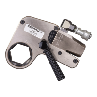
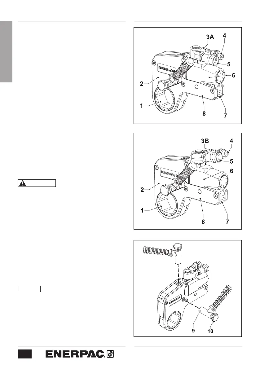
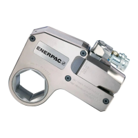
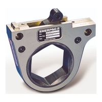
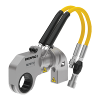
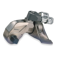
3.1 Overview and features (Fig. 1 or 2)
1 Hexagon ratchet
2 Cassette
3A Hydraulic Swivel (standard)
3B TSP300 Pro Series Swivel (optional)
4 Advance hose connection
5 Return hose connection
6 Hydraulic drive unit
7 Cassette release lever
8 Reaction foot
3.2
To attach the positioning handle
(Fig. 3)
• Secure the positioning handle (9) with
thumb screw (10). Positioning handle can
be installed on either side of wrench or
on top of wrench (as needed).
3.3 Changing the Cassette
WARNING Be sure that hydraulic
pump is OFF and that hydraulic system is
depressurized (0 psi/bar) before removing
or attaching the cassette. Drive unit
could eject under force if this precaution
is not followed, resulting in possible
personal injury.
3.3.1 To Remove the Cassette
(Fig. 4 and 5)
• Be sure the drive unit piston is fully
retracted.
• Firmly grasp the cassette housing
with your hand or place the tool on a
workbench.
NOTICE
Cass
ette will disengage from drive
unit in the following steps. Be sure to support
the cassette so that it does not drop.
• Pull the cassette release lever (7)
outwards.
• Remove the hydraulic drive unit (6) from
the cassette (2).
Fig. 1
Fig. 3
Fig. 2
ENGLISH