2 (Two) Year Limited Warranty
The manufacturer warrants to the original purchaser that its product and component parts will
be free from defects in workmanship and materials for a period of 2 (two) years from the date of
purchase. Return to the original point of purchase for replacement of your product.
Warranty Limitations
This warranty begins at date of purchase.
Warranty is Void if:
The date code is defaced or removed.
The product has a defect or damage due to product alteration, connection to an improper elec-
trical supply, shipping and handling, accident, fire, flood, lightning, or other conditions beyond
the control of the manufacturer.
The product is not installed according to the manufacturers instructions and specifications.
The product has been installed near sources of electromagnetic interference (EMI) such as arc-
ing relay contact.
Owner’s Responsibility
Provide proof of purchase
Provide normal care and maintenance.
Pay for freight, labor and travel.
Pay for service calls related to product installation.
Return any defective product.
In no event shall the manufacturer be liable for incidental or consequential damages.
This warranty gives you specific legal rights and you may have others which vary by state
and/or province. For example, some states and/or provinces do not allow the exclusion or limi-
tation of incidental or consequential damages so this exclusion may not apply to you.
The manufacturer’s continuing commitment to quality products may require a change in specifi-
cations without notice.
This equipment, if installed in strict accordance with the manufacturer's instructions, complies
with the limits for a Class B computing device pursuant to Subpart J of Part 15 of FCC rules.
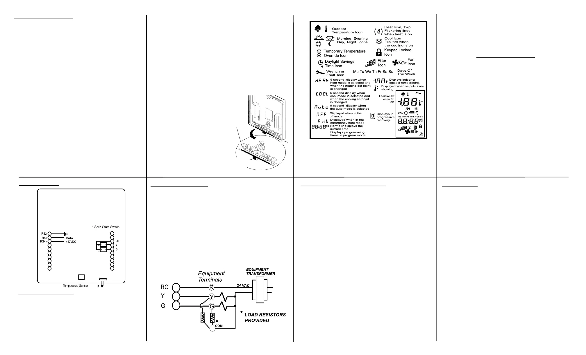
Terminal Designations
RC . . . . . .24 VAC supply from cooling equipment transformer
Y . . . . . . . .Energizes cooling equipment with a call for cooling
G . . . . . . .Fan is energized with a call for cooling or by
pressing the FAN button.
RS2 . . . . .Use to connect up to 6 (SL-IDS) indoor and or 1 (SL-ODT)
RS1 outdoor remote sensor/s.
RS+V When connected the thermostat will automatically use the
the SL-IDS temperature sensor and not its own. Refer to
the instructions included with the sensor.
DIP Switch Options and Functions
Positioning the DIP switches in either the ON or OFF position enables
you to choose between two different options. The DIP switches are
located on the interior of your thermostat and may be accessed by
following the procedure for removing the thermostat from the sub-
base. The following list describes your DIP switch options.
Specifications
Rated Voltage . . . . . . . . . . . 20-30 VAC, 24 nominal
Rated A.C. . . . . . . . . . . . . . . 0.08 Amps to 1.5 Amps continuous
Current per output with surges to 4 Amps Max.
Control Range . . . . . . . . . . .Cooling: 60° to 108°F in 1° Steps
16° to 40°C in 1° Steps
Thermostat
Measurement Range . . . . .28° to 124°F or 0° to 48°C
O.D.T. Displayed
Range . . . . . . . . . . . . . . . . . .-50° to 119°F or -48° to 47°C
Control . . . . . . . . . . . . . . . . .± .5° C at 20°C
Accuracy ± 1°F at 68°F
NOTE: This thermostat contains electronic circuitry replacing the
conventional mechanical anticipator.
Model SC1 111-127 98192
DIP Switch No.
DIP Switch OFF DIP Switch ON
1
2
4 minute minimum ON
Keypad unlock
2 minute minimum ON
Keypad lock
1. 2 Minute or 4 Minute On Times This option allows you to run the
equipment for either a 2 or 4 minute minimum off and on time.
2. Keypad Lock % In the ON position locks out all buttons except the
outdoor temperature button.
Installation Instructions
It is recommended that installation be performed by a qualified installer.
Location
To ensure proper operation, the thermostat should be mounted on an
inside wall in a frequently occupied area of the building. In addition, its
position must be at least 18" (46cm) from any outside wall, and approx-
imately 5' (1.5m) above the floor in a location with freely circulating air
of an average temperature. You should avoid the following locations:
- behind doors or in corners where freely circulating air is unavailable
- where direct sunlight or radiant heat from appliances might affect
control operation
- on an outside wall
- adjacent to, or in line with, conditioned air discharge grilles, stair-
wells, or outside doors
- where its operation may be affected by steam or water pipes or
warm air stacks in an adjacent partition space, or by an
unheated/uncooled area behind the thermostat
- where its operation will be affected by the supply air of an adjacent
unit
- near sources of electrical interference such as arcing relay contacts
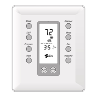
Removing the Thermostat from the Subbase
1. Insert a flat blade screwdriver or a coin 1/8" into the slot located in the
bottom center of the thermostat case and twist 1/4 turn. When you feel
or hear a “click,” grasp the case from the bottom two corners and sepa-
rate from the subbase. Some models require more force than others
when separating due to the number of terminals used.
2. Swing the thermostat out from the bottom.
3. Lift the thermostat up and off the subbase.
4. Place the rectangular opening in the subbase over the equipment con-
trol wires protruding from the wall and, using the subbase as a tem-
plate, mark the location of the two mounting holes (exact vertical
mounting is necessary only for appearance).
5. Use the supplied anchors and screws for mounting on drywall or plaster;
drill 3/16" (5mm) diameter holes at the marked locations; use a hammer to
tap the nylon anchors in flush to the wall surface and fasten subbase using
the supplied screws. (Do not overtighten!)
6. Connect the wires from your system to the thermostat terminals as shown
in the wiring diagrams. Carefully dress the wires so that any excess is
pushed back into the wall cavity or junction box. Ensure that the wires are
flush to the plastic subbase. The access hole should be sealed or stuffed to
prevent drafts from the wall affecting the thermostat.
Replacing the Thermostat on the Subbase
1. Position the thermostat on the hinged tabs at the top of the subbase.
2. Gently swing the thermostat down and press on the bottom center edge
until it snaps in place.
Description Of Icons
Display icons vary according to the model. Your thermostat may not display
all of the icons shown.
Thermostat Cover Lock
If desired, insert the plastic lock
piece into the bottom of the mount-
ed base. The ends of the lock piece
should fit snugly under the lock pins
extending from the bottom of the
mounted base. The tab in the middle
of the lock piece should extend
downward from the mounted base.
To release the locking mechanism,
press the lock piece up and into the
base while gently prying open the
cover at the same time. Use caution
to avoid cracking the thermostat
base or cover.
Plastic
lock pin
Snap plastic
lock into
place
Wiring Diagram
Installing The Resistor (Provided)
Programmable thermostats with solid state equipment outputs require a
minimum of 80 mA AC (0.08A) of current draw to ensure switching integrity.
1. The installer must be a qualified service technician.
2. Read the instructions carefully. Failure to do so may damage the product
or cause a hazardous condition.
3. Connect the resistor leads to the equipment terminal strip across the Y or
G (as required) and the 24VAC common terminals. Avoid contact with any
other terminals or components within the equipment. Connect either end
of the resistor to the terminals (non-polarized) and firmly tighten the screw
terminals.
Notice
The resistor will become warm during equipment operation. This is normal.
9
10 11
12
1615
14
13
Transformer Wiring Diagram
If the transformer
common terminal is
not available, con-
sult the equipment
manufacturer.
The thermostat will be held in the Night program until the
user resets the clock. The thermostat will display AC when the
24 VAC is not supplied. One of the unique features of your ther-
mostat is that there is no battery required to maintain your select-
ed setpoints in the event of a power loss, since the memory is
unaffected by power failures of any duration. There is no reason
to re-program the setpoint temperatures or start times since the
thermostat will retain these program parameters.
Power Outages & Power Failures During Regular Program Schedule
Should your power fail at any time during the regular program, the thermo-
stat will maintain the clock internally for up to 30 minutes. If the power has
not been restored during this time period, the clock will stop. When the
power is restored, the thermostat clock defaults to a flashing 12:00 AM.
 Loading...