INSTALLATION INSTRUCTIONS
-02- -03--01-
DESCRIPTION
FEATURES
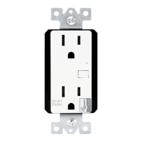
ZW15SM
In-wall Smart Meter
Voltage................................................................................ 120VAC, 60Hz
Resistive..................................................................................1800W(15A)
Motor................................................................................................ 1/2 HP
Z-Wave Frequency.................................................................. 908.42 MHz
Operating Temperature............................................................... 32-104° F
Range.................................................................Up to 100 feet line of sight
SPECIFICA
TIONS
between the Wireless Controller and the closest Z-Wave receiver module.
INSTALLATION
Single Swit
ch Wiring Schematic
Wiring Diagram:
WARNINGS AND CAUTIONS
To be installed or used in accordance with appropriate electrical codes
and regulations. Exercise extreme caution when using Z-Wave devices to
control appliances. Operation of the Z-Wave device may be in a different
please consult a qualified electrician.
room than the controlled appliance, also an unintentional activation may
occur if the wrong button on the remote is pressed. Z-Wave devices may
automatically be powered on due to timed event programming.Depending
upon the appliance, these unattended or unintentional operation could
If you are unsure or uncomfortable about performing the installation,
possibly result in a hazardous condition.
Z-Wave enabled devices should never be used to supply power to, or
control the On/Off status of medical and/or life support equipment.
6. Check connections to be sure they are tight and no bare conductors
are exposed.
7. Insert the ZW15SM switch into the outlet box carefully.
8. Make sure the ZW15SM switch to the box using the supplied screws.
9. Attach the wall plate.
10. Restore power at the circuit breaker and test the system.
Incandescent....................................................................................1000W
Ballast.............................................................................................1200VA
Whit
e (Neutral)
Red
(Load)
ZW15SM
Green (Ground)
Black (Line/Hot)
Wireless Home Automation Control Device
Yellow
Ground
Green
Traveler
White
Neutral
Red
Load (to light fixture)
Black
Hot (from breaker)
OPERATIONS
Air Gap Switch
The ZW15SM has an air gap switch on the lower right side (see diagram)
to completely disconnect power to the load. Slide the air gap switch to left to
operation. The air gap switch must be all the way in for the switch to function and
control the lighting.
Air Gap Switch
LED Light
Switch Paddle
Remote Control
Z-Wave remotes provide control of an Individual device, Groups of devices and Scenes.
Other brands of Z-Wave Certified remotes may not offer as much flexibility in how you
can set up your lighting control network. Please refer to your remote control's instruc-
-tions for details on its capabilities and instructions for adding and controlling devices.
Perfect Replacement for regular wall switch, 120VAC, 15Amp
Wireless Z-Wave technology creates a mesh network for command and
Manual and Remote ON/OFF control of any connected lighting and other
control interoperability with other Z-Wave compliant controller and devices
electrical load
Can be used for single pole or 3- Way (Multi-location) with ZW3K Auxiliary
Air-Gap Switch feature meets UL requirement and disconnect power from
Switch (sold separately)
load locally
The ZW15SM ON/OFF Switch is a perfect wireless manual and remote on/off
control replacement of regular wall switch, controlling incandescent, LED,
ballast and so on. This ZW15SM ON/OFF switch is fully compatible with other
Z-Wave devices, provides programmable function in custom settings such as
scenes, association, schedule event, etc. Also It can be added to most Z-Wave
compliant controllers. As part of any Z-Wave network, each device can be
remotely controlled by commands sent from Z-Wave controllers in real time,
but also act as wireless repeater transmitting RF signal from one to another
intended device, then extending the range of RF signal all over the system.
Sliding Air-Gap switch to a totally disconnect power while replacing light bulbs
and preventing from leakage current from the fixture(s).
4. Disconnect the wiring from the existing switch.
5. Connect the Z-Wave switch as shown in the wiring diagram: Black lead to
hot wire, white lead to neutral wire, red lead to load wire, green lead to
ground wire.
1.WARNING : To avoid fire, shock, or death. Turn off power at circuit breaker
or fuse and test that power is off before wiring.
2. Remove wall plate and existing switch mounting screws.
3. Carefully remove the existing switch from the switch box.
Traveler works with ZW3K for 3-way control, ZW3K sold separated.
3-Way Wiring Schematic using one ZW15SM and one ZW3K
Black (Hot)
Gr
een (Ground)
ZW3K
Red
(Load)
Traveler(Yellow)
White (Neutral)
ZW15SM
disconnect the power while replacing light bulbs and slide it to right for normal
Measures energy usage of the wired load
ON/OFF Switch
MEASURE THE ENERGY USAGE
The ZW15SM Smart Meter Switch enables you to measure the energy
usage of your appliance. When added to a Z-Wave network, the ZW15SM
reports real time data to your gateway or controller. It can also display actual
consumption (in W) and the accumulated power used (in kWh) in the user
interface of the gateway/remote. Please use the gateway installation manual for
specific instructions on measuring the power.