• During the Inclusion/ Exclusion process, the ON/OFF switch is used for including/ excluding the device.
• It is best to perform an Exclusion of the device prior to performing an Inclusion.
Step 1. From the Control Panel, go the the device Exclusion page.
OPERATING THE ZW500DM-PLUS
You're now ready for basic operation of the ZW500DM-PLUS. The Dimmer switch turns the Load (Lights) ON/OFF when the ON/
OFF rocker switch is tapped once. To dim, press and hold the top or bottom switch paddle and release when the desired light level is
achieved. It can also be operated from your desktop or a smart device such as the iPhone, iPad or any Android device. In the event of a
power outage, the ZW500DM-Plus will default to the "OFF" state.
- Push button will respond to ALL-ON and the ALL-OFF command (default).
- Push button will not respond to ALL-ON or ALL-OFF commands.
- Push button will respond to the ALL-OFF command but will not respond to the ALL-ON command.
- Push button will respond to the ALL-ON command but will not respond to the ALL-OFF command.
Configuration details
ZW500DM-PLUS
PROGRAMMING
The process of "Inclusion/ Exclusion" is to Add or Remove the device from the Hub. All Z-Wave devices must be
"Included" on the Controller (Hub) before it can be controlled from a smart device. The Hub should be brought
physically closer to the device just for the "Inclusion" process (recommended within 10ft). When finished, the
Hub and device can be moved back to final installation location. Download the App or log onto the website
associated with the Hub you are using and follow their Inclusion/ Exclusion instructions as each Hub's
programming and features are different.
ADVANCED PROGRAMMING
WARNING: Advanced programming is recommended ONLY for experienced programmers. The ZW500DM-PLUS has customizable features /
functions that require writing codes. Changes to code may cause device to function improperly or to not function at all.
The following parameters require that you have an advanced controller. Basic remotes do not have this capability.
LED Light and Buttons Configuration
By default, one press of the "up" button will turn the Load on and the LED
indicator will turn off. Use "Command_Class_Configuration" to configure the LED
indicator to operate in reverse when the button is pressed.
o Select "Exclude Device".
o When prompted, press the "ON" or "OFF" paddle on the switch 3 times.
Step 2. Go to the "Add Device" page.
o Select "Include Device".
o When prompted, press the "ON" or "OFF" paddle on the switch 3 times.
o Once the exclusion is finished, the blue LED indicator will start blinking.
The primary controller should indicate that the action was successful. If the controller indicates the action was unsuccessful,
please repeat from Step 1. Once the switch is part of the network, the same basic procedure is used to add the switch to groups &
scenes or change advanced functions. Refer to the primary controller’s instructions for details.
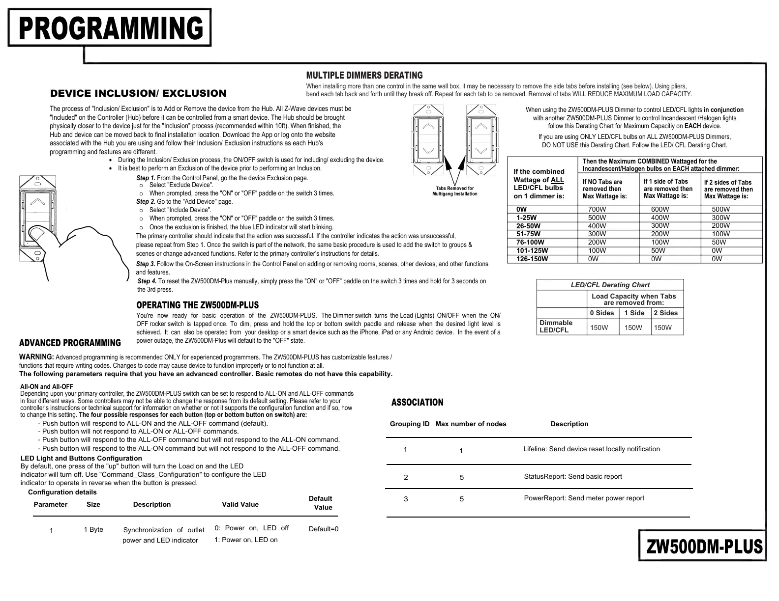
MULTIPLE DIMMERS DERATING
When installing more than one control in the same wall box, it may be necessary to remove the side tabs before installing (see below). Using pliers,
bend each tab back and forth until they break off. Repeat for each tab to be removed. Removal of tabs WILL REDUCE MAXIMUM LOAD CAPACITY.
Dimmable
LED/CFL
Load Capacity when Tabs
are removed from:
0 Sides 1 Side 2 Sides
150W 150W 150W
LED/CFL Derating Chart
Then the Maximum COMBINED Wattaged for the
Incandescent/Halogen bulbs on EACH attached dimmer:
If NO Tabs are
removed then
Max Wattage is:
If 1 side of Tabs
are removed then
Max Wattage is:
If 2 sides of Tabs
are removed then
Max Wattage is:
0W
1-25W
26-50W
51-75W
76-100W
101-125W
126-150W
700W
500W
400W
300W
200W
100W
0W
600W
400W
300W
200W
100W
50W
0W
500W
300W
200W
100W
50W
0W
0W
If the combined
Wattage of ALL
LED/CFL bulbs
on 1 dimmer is:
When using the ZW500DM-PLUS Dimmer to control LED/CFL lights in conjunction
with another ZW500DM-PLUS Dimmer to control Incandescent /Halogen lights
follow this Derating Chart for Maximum Capacitiy on EACH device.
If you are using ONLY LED/CFL bulbs on ALL ZW500DM-PLUS Dimmers,
DO NOT USE this Derating Chart. Follow the LED/ CFL Derating Chart.
All-ON and All-OFF
Depending upon your primary controller, the ZW500DM-PLUS switch can be set to respond to ALL-ON and ALL-OFF commands
in four different ways. Some controllers may not be able to change the response from its default setting. Please refer to your
controller’s instructions or technical support for information on whether or not it supports the configuration function and if so, how
to change this setting. The four possible responses for each button (top or bottom button on switch) are:
Step 3. Follow the On-Screen instructions in the Control Panel on adding or removing rooms, scenes, other devices, and other functions
and features.
Step 4. To reset the ZW500DM-Plus manually, simply press the "ON" or "OFF" paddle on the switch 3 times and hold for 3 seconds on
the 3rd press.
DEVICE INCLUSION/ EXCLUSION
Description Valid Value
1 Byte
Default
Value
1
Default=0
Synchronization of outlet
power and LED indicator
0: Power on, LED off
1: Power on, LED on
Parameter
Size
ASSOCIATION
Grouping ID Max number of nodes
Description
1
1
Lifeline: Send device reset locally notification
2 5
StatusReport: Send basic report
3 5
PowerReport: Send meter power report
 Loading...