Install conduit and eld wiring
+
DANGER! Risk of electric shock. The DC switch must be in the
Locked position before performing this step.
A ) If not already done, use a Phillips screw driver to loosen the screws
securing the eld wiring compartment cover and remove the cover. Keep
the cover and screws handy as you will need them later.
B ) Remove the sealing plug for entry into the eld wiring compartment.
If installing only one battery or when installing the last battery in the
array, seal up the hole with the supplied sealing plug.
C ) Size the conductors (Lines and Ground) to account for voltage rise
and to conform to the tables below. Design for a voltage rise total of
less than 2%. Encharge can use any circuit breaker size between 10 A
and 40 A. Breaker rating and wire size are installation dependent.
Number of
Encharge 3
Batteries
Current (A) Minimum Wire
Size (AWG)
Breaker Handle
Rating (A)
1 5.3 14 10
2 10.7 14 15
3 16.0 12 20
4 21.3 10 30
5 27.7 8 35
6 32.0 8 40
Number of
Encharge 10
Batteries
Current (A) Minimum Wire
Size (AWG)
Breaker Handle
Rating (A)
1 16.0 12 20
2 32.0 8 40
+ DANGER! Risk of electric shock. Check that the dedicated circuit
breaker protecting the branch where the Encharge Battery(ies) will
be connected is turned off before wiring.
* WARNING! Risk of equipment damage. The DC switch must be
OFF before installing, otherwise Encharge will try to form a grid.
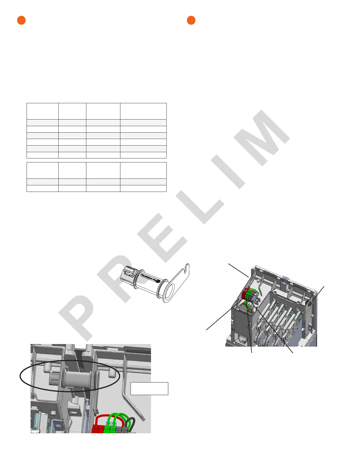
D ) If installing an Encharge 10, install the inter-unit raceways. The
left-side and right-side conduit openings are different diameters, so
you must install the raceway in the proper direction.
•
Face the fronts of the batteries, and insert the raceway through
the right-hand unit’s left-side conduit opening from within the eld
wiring compartment, with the arm of the raceway pointing up.
•
Push the raceway through the right-hand unit’s
left-side conduit opening and into the left-side
unit’s right-side conduit, opening until the two
snap features on the raceway engage the
left-side unit’s enclosure.
•
Once fully inserted, rotate the “arm” toward you
until it stops.
•
The left-side conduit opening of each battery unit has a at surface,
without additional features. The larger seal (green) on the raceway
mates with this opening. The right-side conduit opening has a
groove around the hole to t the O-ring (red) of the raceway. Make
sure that the O-ring is captured in the groove between the Encharge
enclosure and the raceway ange adjacent to the O-ring.
6
Install conduit and eld wiring, continued
E ) Using the conductors and suitable conduits, connect the AC
disconnect and the rst adjacent Encharge Battery. Use the conduit
openings provided to connect the conduit and pass the wires
through them. Note that if an Enphase Enpower is in line-of-sight,
the breaker can service as a disconnect.
* WARNING! Risk of equipment damage. Do not modify or rewire
the pre-installed wiring or bonding connections in the eld wiring
compartment.
* WARNING! Risk of equipment damage. Always connect to two
Lines (active) and one ground.
F ) Connect each wire in the eld wiring compartment to its corre-
sponding conductor (Lines and Ground). Each terminal accepts two
12-8 AWG conductors (11mm/7/16 inch strip length). Tighten to 14
lb-in.
G ) If installing an Encharge 10, route the wires from the rst Encharge
Battery to the adjacent Encharge Battery through the inter-unit
raceway. There are two positions for each line and for ground in the
terminal block to allow for daisy-chaining.
* WARNING! Risk of equipment damage. Do not daisy chain
more than six total Encharge 3 or two Encharge 10 on a single
branch circuit.
H ) After all wires in the eld wiring compartment are connected and
secured, check that there are no exposed conductors.
I ) If connecting additional Encharge Batteries, use another conduit and
another set of wires to connect between eld wiring compartments.
J ) Gently arrange all the wires and connectors inside the eld wiring
compartment.
K ) Plug any unused conduit openings before proceeding.
L ) Replace the eld wiring compartment cover. Use a cross-head
screw driver to tighten the cover screws to 2.3Nn (20.3 Ib-in).
* WARNING! Risk of equipment damage. Ensure that no wires are
pinched before replacing the cover.
+
DANGER! Risk of electric shock. The system is not ready to
be energized! Do not close the circuit breaker or turn on the DC
switch.
6
KEY:
1. AC (conduit opening). Used for inter-unit raceway when an
adjacent battery is installed.
2. AC (conduit opening)
3. Terminal for L1 in from conduit opening
4. Terminal for ground in from conduit opening
5. Terminal for L2 in from conduit opening
2
1
3
4
5
Inter-unit
raceway
Correctly installed
inter-unit raceway
 Loading...