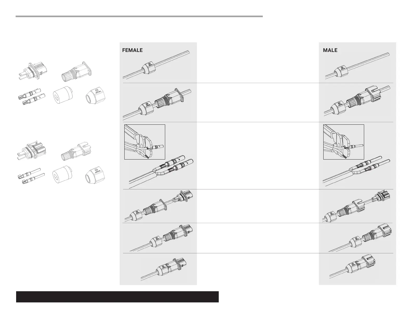
B) Make sure the gasket is pre-installed inside the
cover, then slide the cover and gasket over the
cable.
C) Attach the terminals to the cable:
• Strip the outer jacket to 32 mm (1.25 in.) and strip the
inner insulation to 9.5 mm (3/8 in.).
• Load the open end of each terminal in the 12 gauge
slot of the crimp tool, ush with the edge of the slot.
• Crimp the end of the terminal over the stripped copper
wires.
• Do NOT crimp over insulation.
D) Insert terminals into connector body. Each terminal
should click into place.
E) Assemble connector body and cover. Listen for a click
as they engage.
F) Tighten the nut to 7 Nm with channel lock pliers or a torque
wrench.
Connector body
Terminals
Cover
Nut
FEMALE CONNECTOR PARTS
MALE CONNECTOR PARTS
Gasket
Connector body
Terminals
Cover
NutGasket
A) Slide the nut over the cable.
PARTS
© 2017 Enphase Energy. All rights reserved.
Enphase Customer Support: enphase.com/en-us/support/contact
ASSEMBLY
Follow the steps to assemble Enphase Field-Wireable Connectors.
FEMALE MALE
*
WARNING: Risk of equipment failure. Do not
mix male and female connector parts when
assembling connectors.