signal is interrupted. If the triggering signal is interrupted before the
adjusted me t, the counted me is erased. The me is restarted when
the triggering signal is applied again.
F OFF Delay: When the supply voltage is applied, the output relay
switches into ON posion and the adjusted me t is started to count.
The output relay switches into OFF posion at the end of the me t.
This status remains unl the supply voltage is interrupted. If the supply
voltage is interrupted before the expiry of the adjusted me, the me
already expired is erased and is restarted when the supply voltage is
applied again.
G Symmetric Flasher: When the supply voltage is applied, the
adjusted me t is started to count. The output relay switches into ON
posion at the end of the me t and the adjusted me counts again.
The output relay switches into OFF posion at the end of the me t.
This cycle counnues ll the supply voltage is interrupted.
Please, see the page 4 for me diagrams.
④Supply LED: When the supply voltage is applied, ON LED on the
device illuminates. When the supply voltage is interrupted, ON LED
exnguishes.
⑤Relay LED: When the output relay is ON posion, OUT LED on the
device illuminates. When the output relay is OFF posion, OUT LED
exnguishes.
Technical Data
Rated Voltage (Un) : 12 – 240 VAC/DC
Rated Frequency : 50/60 Hz
Output Contacts : 1 CO, 8 A, 2000 VA (cosϕ=1)
Terminals : A1(+), A2(-)
Delay Time : 0.1 sec – 100 hours
Ambient Temperature : -5 °C / + 50 °C
Protecon Class : IP20
Mechanical Life : 1 x 10⁷ OPS
Electrical Life :
1 x 10⁵ OPS (8A 250VAC, 85°C resisve load)
Dimensions : Type PK 22
Installaon : Surface mounng or on the mounng rails
Weight : 57 gr
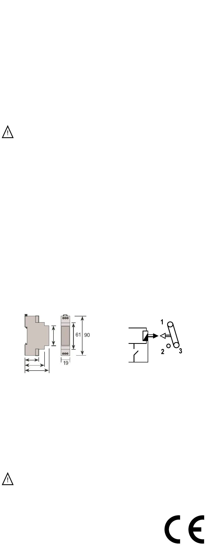
Dimensions Connecon Diagram
A1(+)
B1
24-240
VAC/DC
A2(-)
27,5
45,6
58
48
Precauons for Installaon and Safe Use
Failure to follow those instrucons will result in death or serious injury.
• Disconnect all power before working on equipment.
• When the device is connected to the network, do not remove the
front panel.
• Do not clean the device with solvent or the like. Only clean the
device with a dried cloth.
• Verify correct terminal connecon when wiring.
• Electrical equipment should be serviced only by your competent
seller.
• Mount device to panel.
No responsibility is assured by the manufacturer or any its
subsidiaries for any consequences arising out the use of this
material.
Note: The contact resistance at ohmic load (e.g.: Incandescent bulb,
Resistance devices) is 8A. It is recommended to use a contactor if the
inducve load (e.g.: AC motor, uorescent, etc.)
or capacive load (e.g. : Led Drivers,
UPS, Fluorescent(Electronic Ballast), etc.) switch.
Otherwise adhesion may occur in relay contacts.
ZAMAN RÖLELERİ
MCB-20 Zaman Rölesi
TIME RELAYS
MCB-20 Time Relay
MCB-20 zaman rölesi 12-240 VAC/DC geniş besleme aralığı, 0.1
saniyeden 100 saate kadar ayarlanabilen zaman skalası ve 7 farklı
zaman fonksiyonu ile endüstriyel ve yerel uygulamalarda kullanılır.
① Zaman Çarpanı Ayarı: Seçilen zaman diliminin çarpılacağı zaman
çarpanıdır. Cihaz üzerinde bulunan ayar trimpotu ile 0.1’den 1’e kadar
ayarlanır.
②Zaman Dilimi Ayarı: Seçilen zaman bölgesinin maksimum değerini
gösterir. Ayarlanmak istenen çalışma süresine göre 8 farklı zaman
diliminden seçim yapılır.
Çalışma süresi = Zaman dilimi x Zaman çarpanı
Örnek: Çalışma süresi 30 saniye olarak ayarlanmak isteniyorsa,
T = 100 x 0.3
T = 30 saniye
③Fonksiyon Ayarı: Cihazın çalışğı zaman fonksiyonu gösterir.
A Çekmede Gecikmeli: Besleme gerilimi uygulandığında ayarlanan t
bekleme süresi saymaya başlar. t süresinin bitmesinin ardından röle
çıkışı ON konumuna geçer. Cihazın besleme gerilimi kesilene kadar
röle çekili konumda kalır. t süresi bitmeden besleme gerilimi kesilirse,
sayılmış zaman silinir ve besleme gerilimi tekrar uygulandığında t
süresi tekrar saymaya başlar.
B Kontrol Girişli Bırakmada Gecikmeli: Besleme gerilimi ve tekleme
sinyali uygulandığında röle çeker. Tekleme sinyali kesildiğinde t
süresi saymaya başlar ve süre sonunda röle bırakır. t süresi bitmeden
tekrar sinyal uygulandığında sayılan süre silinir ve tekleme sinyalinin
kesilmesiyle birlikte yeniden saymaya başlar.
C Basarken Teklemeli Bırakmada Gecikmeli: Besleme gerilimi ve
tekleme sinyali uygulandığında röle çeker ve ayarlanan t süresi
saymaya başlar. Ayarlanan t süresi sonunda röle bırakır. t süresi
boyunca tekleme sinyali cihazın çalışmasını etkilemez. t süresi
bikten sonra tekleme sinyali bir sonraki döngüyü başlar.
D Bırakırken Teklemeli Bırakmada Gecikmeli: Besleme gerilimi
uygulandığında tekleme sinyalinin uygulanması cihazın konumunu
etkilemez. Tekleme sinyalinin kesilmesi ile röle çeker ve ayarlanan t
süresi saymaya başlar ve süre sonunda röle bırakır. t süresi boyunca
tekleme sinyali cihazın çalışmasını etkilemez. t süresi bikten sonra
tekleme sinyali bir sonraki döngüyü başlar.
E Kontrol Girişli Çekmede Gecikmeli: Besleme gerilimi ve tekleme
sinyali uygulandığında ayarlanan t süresi saymaya başlar. t süresi
sonunda röle çeker ve cihazın beslemesi veya tekleme sinyali
kesilene kadar röle konumunu korur. Eğer tekleme sinyali ayarlanan
t süresinden önce açılırsa sayılan zaman silinir. Tekleme sinyali tekrar
uygulanadığında süre baştan saymaya başlar.
MCB-20 me relay uses in industrial and domesc applicaons with
12-240 VAC/DC wide operang range, adjustable me range from 0.1
seconds to 100 hours and 7 dierent ming funcons.
① Time Mulplier Adjustment: It is the me mulplier that the
selected me range is mulplied. It is set from 0.1 to 1 with the
adjustment trimpot on the device.
②Time Range Adjustment: It shows the maximum value of the
selected me range. One of 8 dierent me range is selected
according to the operaon me to be set.
Operaon me = Time range x Time mulplier
Example: If it is wanted to be set operaon me to 30 seconds,
T = 100 x 0.3
T = 30 seconds
③Funcon Adjustment: It shows the funcon of the device.
A ON Delay: When the supply voltage is applied, the adjusted me t
is started to count. Aer the adjusted t has expired, the output relay
switches into ON posion. This status remains unl the supply voltage
is interrupted. If the supply voltage is interrupted before the expiry of
the adjusted me, the me already expired is erased and is restarted
when the supply voltage is applied again.
B OFF Delay with Control Input: When the supply voltage and
the triggering signal are applied, the output relay switches into ON
posion. When the triggering signal is interrupted, the me t is started
to count and the output relay switches into OFF posion at the end of
the me. If the triggering signal is applied again before the me t has
expired, the me already expired is erased. The me restarts again
when the triggering signal is interrupted.
C Single Shot Leading Edge with Control Input: When the supply
voltage and the triggering signal are applied, the output relay switches
into ON posion and the adjusted me t is started to count. The
output relay switches into OFF posion at the end of the adjusted me
t. During the adjusted me, the triggering signal is not aected the
working of the device. At the end of the me t, the triggering signal
starts the next cycle.
D Single Shot Trailing Edge with Control Input: When the supply
voltage is applied, applying the triggering signal has no inuence
on the condion of the output relay. When the triggering signal
is interrupted, the output relay swithed into ON posion and the
adjusted me t is started to count. The output relay switches into
OFF posion at the end of the me. During the adjusted me, the
triggering signal has not aected the working of the device. At the end
of the me t, the triggering signal starts the next cycle.
E ON Delay with Control Input: When the supply voltage and the
triggering signal are applied, the adjusted me t is started to count.
The output relay switches into ON posion at the end of the adjusted
me and this status remains unl the supply voltage or the triggering
F Bırakmada Gecikmeli: Besleme gerilimi uygulandığında röle çeker
ve ayarlanan t süresi saymaya başlar. t süresi sonunda röle çıkışı
OFF konumuna geçer. Cihazın besleme gerilimi kesilene kadar röle
konumunu korur. t süresi bitmeden besleme gerilimi kesilirse sayılmış
zaman silinir ve besleme gerilimi tekrar uygulandığında t süresi tekrar
saymaya başlar.
G Simetrik Flaşör: Besleme gerilimi uygulandığında ayarlanan t süresi
saymaya başlar. t süresi sonundan röle çeker ve ayarlanan t süresi
tekrar saymaya başlar. Süre sonunda röle bırakır. Besleme gerilimi
kesilene kadar bu döngü devam eder.
Zaman diyagramları için sayfa 4 ‘e bakınız.
④Besleme ışığı: Besleme gerilimi uygulandığında cihaz üzerindeki
ON LED’i yanar. Besleme gerilimi kesildiğinde ON LED’i söner.
⑤Röle ışığı: Röle çekili konumdayken cihaz üzerindeki OUT LED’i
yanar. Röle kontağını bırakğında OUT LED’i söner.
Teknik Bilgi
Işletme Gerilimi (Un) : 12-240 VAC/DC
İşletme Frekansı : 50/60 Hz
Çıkış Kontağı : 1 CO, 8 A, 2000 VA (cosϕ=1)
Klemensler : A1(+), A2(-)
Zaman Aralığı : 0.1 sn – 100 saat
Ortam Sıcaklığı : -5 °C / + 50 °C
Koruma Sını : IP20
Mekaniksel Ömür : 1 x 10⁷ OPS
Elektriksel Ömür :
1 x 10⁵ OPS (8A 250VAC, 85°C’de dirençli yük)
Boyutlar : Tip PK 22
Bağlan Şekli : Pano içine dikey veya klemens rayına
Ağırlık : 57 gr
Boyutlar Bağlan Şeması
A1(+)
B1
24-240
VAC/DC
A2(-)
27,5
45,6
58
48
Güvenli Kullanım ve Kurulum İçin Uyarılar
Aşağıdaki talimatlara uyulmaması halinde yaralanma ve ölümle
sonuçlanabilecek durumlar ortaya çıkabilir.
• Cihaz üzerindeki herhangi bir işlemden önce tüm besleme
gerilimlerini kesiniz.
• Cihaz şebekeye bağlı iken ön paneli çıkarmayınız.
• Cihazı solvent veya benzeri maddelerle temizlemeyiniz. Cihazı
temizlemek için sadece kuru bez kullanınız.
• Cihazı çalışrmadan önce bağlanlarının doğru olduğunu kontrol
ediniz.
• Cihazınızdaki herhangi bir sorunda yetkili sacınızla temas kurunuz.
• Cihazı panoya monte ediniz.
Yukarıdaki önlemlerin uygulanmaması sonucu doğabilecek
istenmeyen durumlardan üreci rma hiç bir şekilde sorumlu
tutulamaz.
Not: Kontak dayanımı omik yükte (ör = Akkor emanlı ampul, Rezistanslı
cihazlar) 8A’dir. Endükf (ör = AC motor, orasan (Sargılı balaslı), vb..)
ya da Kapasif (ör = Led Sürücüler, UPS, orasan(Elektronik Balastlı),
vb..) yük anahtarlanacaksa kontaktör kullanılması tavsiye edilir. Aksi
takrde cihazın röle kontaklarında yapışma meydana gelebilir.
Bu ürün, 30.05.2008 tarih ve 26891 sayılı resmi gazetede
yayınlanan EEE Yönetmeliğinin Madde 2 ve Ek-1A
madde 9 kapsamındadır.
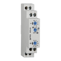
①
Time Mulplier
Adjustment
② Time Range
Adjustment
③ Funcon
Adjustment
④ Supply LED
⑤ Relay LED
① Zaman çarpanı
ayarı
② Zaman dilimi
ayarı
③ Fonksiyon ayarı
④Besleme ışığı
⑤Röle ışığı
 Loading...