8
ENVISION POOL HEATER INSTALLATION MANUAL
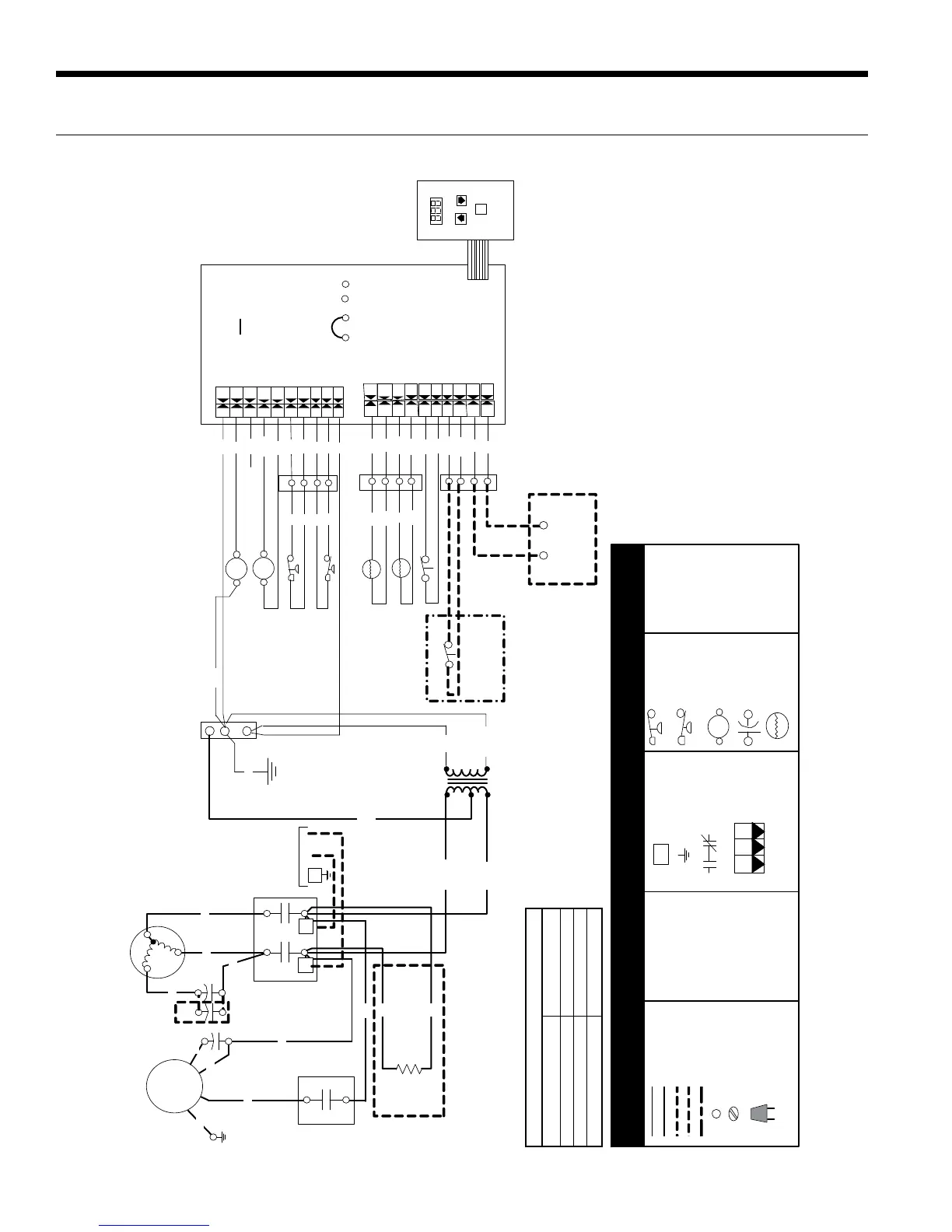
NOTES:
Use only copper conductors.1.
Connect field wiring in grounded rain-tight conduit, 2.
per rating plate.
Connect bond wire to pool steel using #8 solid 3.
copper wire or larger.
All wiring must conform to national (NEC) and local 4.
electrical codes.
2 - Only on 080 models.
Factory low voltage wiring
Switch -High pressure
Switch -Low pressure
Relay coil
Field wire lug
Ground
Relay Contacts -
N.O., N.C.
Polarized connector
Notes:
Factory line voltage wiring
Field low voltage wiring
Field line voltage wiring
Optional block
Quick connect terminal
Wire nut
Screw terminal -
field connection
CC - Compressor contactor
HP - High pressure switch
LP - Low pressure switch
Fan - Fan relay
L1
1
3
2
P
FS1 - Flow Switch 1
Capacitor
FS2 - Flow Switch 2
DC - Defrost Cycle
WT - Water Temperature
T
Thermistor
RM - Remote Automation
Microprocessor Control
TEST
PIN
CC
HP
LP
DC
WT
FS1
FS2
Field Installed Flow
Switch. See Table 1.
Remote Automation Jumper
P1
P2
P3
PIN 1 2 3
Field Installed home
automation control. See
Tabl e 1.
See Table 1
Fan1
Interface Panel
9
10
11
12
TS
4
Green
7
8
1
2
TS
3
4
5
6
24
LP
LP
HP
HP
CC
CCG
F2
F1
C
PIN 1
X3
X3
X2
X2
X1
X1
WAT
WAT
FP
FP
Compressor
Unit
Po wer Su pply
208-230/60/1
CC
T1
L1
T2
L2
G
C
R
S
RB
Fan Motor
2
4
Transformer
24V
Bl ack/White
Yellow
Blue
230 V
Black
Com
PS
C
D
A
Red
208 V
Black
Blue
Brown
Bl k/Wht
Violet
Black
Black
Blue
Bl ue
Red
Black
Yellow
Violet
Violet
Orange
Orange
Gray
Gray
P5
1
Brown
Cap
Cap
Not Used
Yellow
Bl ack
Gree n
Black
Brown
Orange
Blue
Red
Bl ack
Blue
Blue
Red
Red
Black
Black
Red
Black
Crankcase
Heater
Black
Black
Orange
Note 1
1 - Only on 105 models.
PTCR
Note 2
Ye llow
Bl ack
Table 1 - Jumper Configurations
Application
Pool/Spa (1 Valve)
Pool/Spa (2 Valve)
Remote Automation
Jumper Setting
1 & 2
2 & 3
3 & 4
Legend
97P675-01 12/1/09
230/60/1
Wiring Schematic
 Loading...