EPSON Stylus PHOTO 2100/2200 Revision B
DISASSEMBLY AND ASSEMBLY Disassembly 141
5. Remove the three screws 6) C.B.S 3×6 (9±1kgf.cm) that secure the Cutter Support,
and remove the Cutter Support from the Printer Mechanism.
Figure 4-44. Screws That Secure the Cutter Support
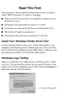
6. Remove the three screws 6) C.B.S 3×6 (6±1kgf.cm) that secure the Front Frame.
Figure 4-46. Screws That Secure the Front Frame
" Insert the cutouts in the left and right of the Upper Housing
Mounting Plate into the notches of the Front Frame, and hitch
the cutout of the Upper Housing Mounting Plate on the notch in
the center of the Front Frame.
Refer to Figure 4-42, "Removing the Upper Housing Mounting
Plate".
Figure 4-43. Reinstalling the Upper Housing Mounting Plate
Compression Spring 2.45
Joggle
Front Frame
rear center
C.B.S 3×6
Joggle
Joggles Joggles
Cutter
Support
" When reinstalling the Cutter Support, insert the four joggles
securely to fix the Cutter Support.
Refer to Figure 4-44, "Screws That Secure the Cutter Support".
" After reinstalling the Cutter Support, make sure that it is in the
normal position since the Paper Eject Unit left side may come off
the engagement portions with the Left and Right Frames and
shift to the printer left side during installation of the Cutter
Support.
Refer to Figure 4-45, "Normal Positions of Paper Eject Unit
Engagement Portions".
Figure 4-45. Normal Positions of Paper Eject Unit
Engagement Portions
Normal position of right
side engagement portion
Printer front
Paper Eject Unit
Normal position of left
side engagement portion
Joggle
C.B.S 3×6
Front Frame
Joggle
C.B.S 3×6

 Loading...