EPSON Stylus PHOTO 2100/2200 Revision B
DISASSEMBLY AND ASSEMBLY Disassembly 157
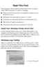
" When reinstalling the Shaft Fixing Plate to the Carriage Guide
Shaft A, refer to Figure 4-82 since it will come off if reinstalled
incorrectly. (As in the Carriage Guide Shaft B)
Figure 4-82. Reinstalling the Shaft Fixing Plate
"
Reinstall the Carriage Unit and Carriage Guide Shaft A
correctly so that the Timing Belt is not twisted.
Carriage
Guide
Shaft A
Shaft
Fixing
Plate
A D J U S T M E N T
R E Q U I R E D
" When removing the Carriage Unit, the following adjustments
are necessary. Make the adjustments in the following order.
1. PG adjustment
2. CR tooth skip prevention mechanism adjustment
3. Head cleanig
4. Head angular adjustment
5. Bi-D adjustment
6. Pixel Shift Adjustment
" Refer to "Chapter 5 Adjustment" for the adjustment
procedures.
" After changing the following parts for new ones, always apply
grease G-26 or oil O-12 in the specified positions.
• Driven Pulley Holder:
Refer to Chapter 6, Figure 6-4, "Lubrication Point 2".
• Driven Pulley:
Refer to Chapter 6, Figure 6-5, "Lubrication Point 3".
• Oil Pad, Oil Pad Ring:
Refer to "Chapter 6, Figure 6-14, "Lubrication Point 16".
• Left Adjust Parallelism Bush:
Refer to Chapter 6, Figure 6-19, "Lubrication Point 21".
• Right Adjust Parallelism Bush:
Refer to Chapter 6, Figure 6-20, "Lubrication Point 22".

 Loading...