EPSON Stylus PHOTO 2100/2200 Revision B
DISASSEMBLY AND ASSEMBLY Disassembly 183
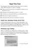
3. Pull and release the Joggle Supports, which secure the left and right of the Cutter
Housing, to the front as seen from the Cutter Housing rear, and remove the Cutter
Housing.
Figure 4-139. Joggle Supports That Secure the Cutter Housing
4. Disconnect the Connector Cables (CN3, CN4) from the left and right Cutter
Sensors.
5. Remove one (a total of two) screw 6) C.B.S 3
×6 (9±1kgf.cm) that secures each of
the left and right Cutter Sensors, and remove the Cutter Sensors.
Figure 4-141. Screws That Secure the Cutter Sensors
When reinstalling the Cutter Housing, match the two inner screws
with the screw holes of the Harness Clamp as viewed from the
Cutter Housing rear. (This also applies to the left side.)
Refer to Figure 4-140, "Reinstalling the Cutter Housing".
Figure 4-140. Reinstalling the Cutter Housing
Joggle Supports
Matched portion
Before reinstalling each of the Cutter Sensors, match it to the two
(a total of four) joggles.
Refer to Figure 4-142, "Reinstalling the Cutter Sensors".
Figure 4-142. Reinstalling the Cutter Sensors
C.B.S 3x6
Connector
C.B.S 3x6
Connector
Cutter Sensor Cutter Sensor
Joggles
Joggles

 Loading...