EPSON Stylus COLOR 680/777/777i Revision B
Disassembly and Assembly Disassembly 69
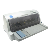
6. Remove two screws (C.B.P-TITE 3x6 F/Zn and +Bind B-TITE SEMS W2 2.5x5
F/Zn) tighiening the Printhead.
Figure 4-7. Removing the two screws tightening the Printhead
7. Remove the Printhead from the CR unit.
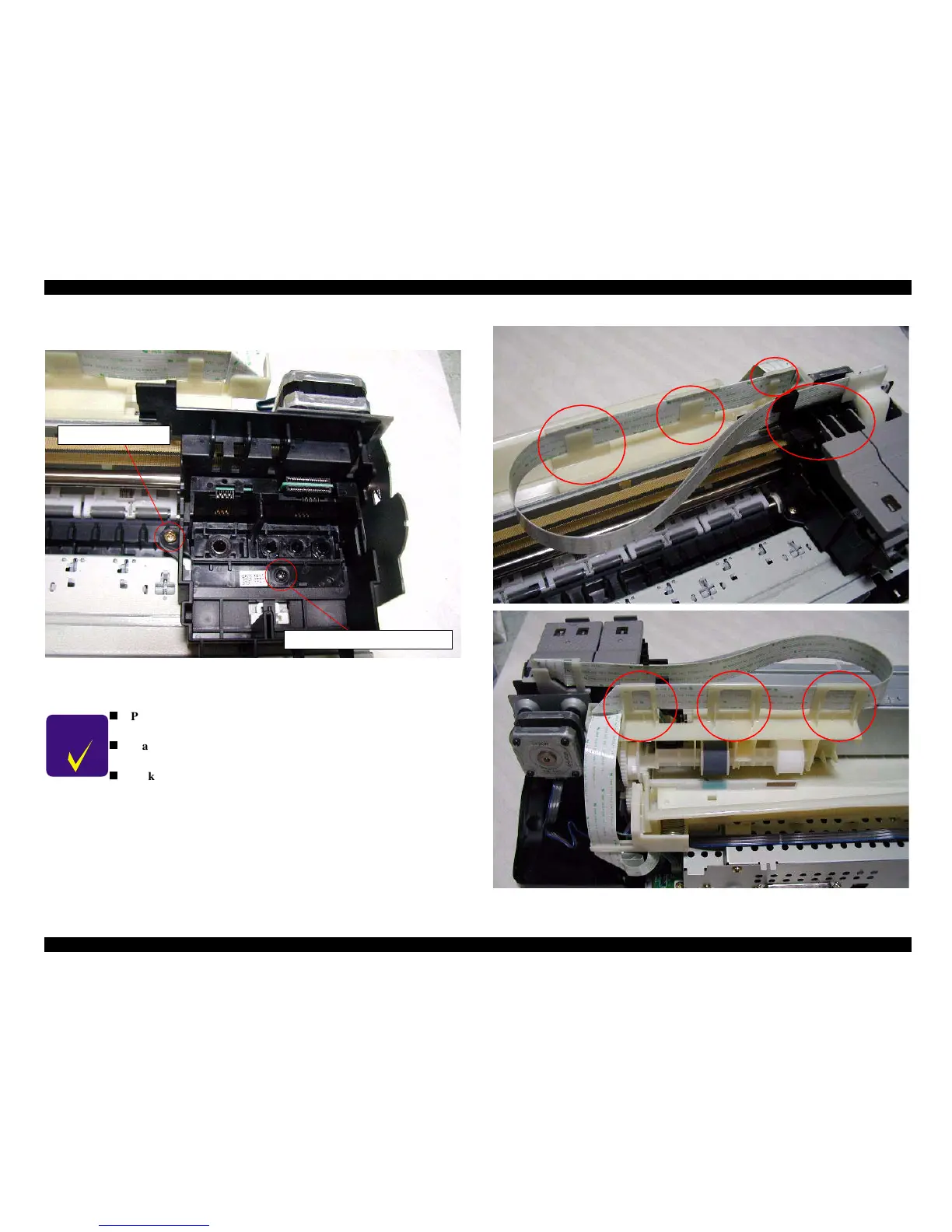
Figure 4-8. Placing the Printhead’s FFC
C H E C K
P O I N T
n
Place the Printhead’s FFC in the cable holder by the four
portions indicated in the following Figure4-8.
n
Make sure that the Head Grounding Plate is installed to the
carriage correctly. Refer to Figure 4-9.
n
Make sure that two holes of the Printhead correctly fit in the
installing position pins. Figure 4-9.
C.B.P-TITE 3x6 F/Zn
+BindB-TITESEMSW22.5x5F/Zn

 Loading...