EPSON AcuLaser C9200N Revision D
OPERATING PRINCIPLES Operating Principle of Main Unit Mechanism 48
Confidential
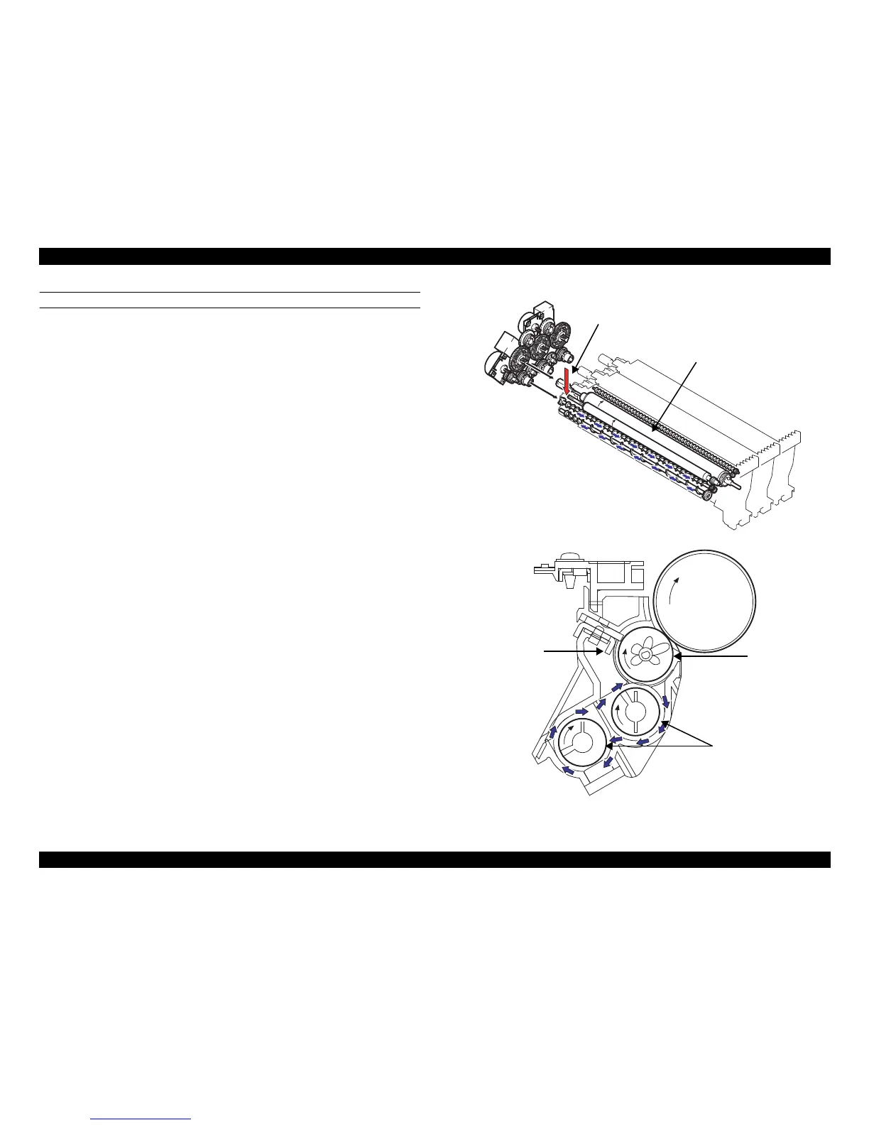
DEVELOPER FLOW
1. Toner supplied from the rear end of the Developing Unit is fed to the lower screw.
It is then fed to the front of the unit, while being mixed with developer and
electrically charged by the Supply/Agitating/Conveying Screws.
2. The TCR Sensor installed on the underside of the Developing Unit detects toner-to
carrier ratio during this time.
3. The developer, fed to the front of the Developing Unit, is conveyed further to the
upper screw.
4. The Toner sticks to the electrostatic latent image on the surface of the PC Drum.
The developer that is left on the Sleeve is returned to the lower screw by the
magnetic pole positioning of the Developing Roller. It is then conveyed to the rear
side of the Photoconductor Unit.
Figure 2-22. Developer flow (For PU/Y)

 Loading...


