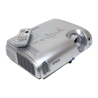
2-12
EMP-S4
SEIKO EPSON Revision:B
2.5.2 Overview of Operation
The output cable of the power supply unit is connected to CN2000 on the MA board. It allows
the following voltages and signals to be transmitted.
• DC output
• The power supply On/Off signal (PWON)
The power supply fan reduces the internal heat in the power supply unit. The heated air
discharged from the power supply unit is then exhausted with the exhaust fan connected to
CN706 on the MA board.
C A U T I O N
Background power is still supplied to the MA board through CN2000
connector as long as the power cord is connected to the projector, even if the
[Power] switch is turned off.
The EMI filter/regulator circuit eliminates interference (noise) from the AC
line and generates the DC voltage for the regulators.
The DC voltages shown in the tables below are generated by a Switching
Regulator. No fluctuations in output potential occur as a result of load
fluctuations, and the individual output voltages cannot be adjusted.
Table 2-2.
Output voltage
Output
voltage
accuracy
Ripple
(mVpp)
Ripple/
Spike
(mVpp)
Output current Protection circuit
Load capac-
ity (Refer-
ence) (µF)
Signal
name
Voltage
Standby
mode
Min Typ
Over-
voltage
Over-
current
+5 +5 V ±5 % 100 200
20 mA to
220 mA
20 mA 3.5 A -
Shutoff
100
+7 +7.2 V
+0.8 V/-
-0.4 V
100 200 0 A 0 A 0.5 A -
Shutoff
200
+13 +13.8
+15 V ~
+13.5 V
200 300 0 A 0.2 A 1.5 A -
Shutoff
100+470
+18 +1.8
+16 V ~
+23 V
400 400 0 A 0.2 A 0.45 A -
Shutoff
47
Ballast
Output
380 VDC
360-400
VDC
25 Vpp 25 Vpp
(0.1) (0.1) 250 W
410 V Shutoff

 Loading...