REV.-A
PRINCIPLES OF OPERATION
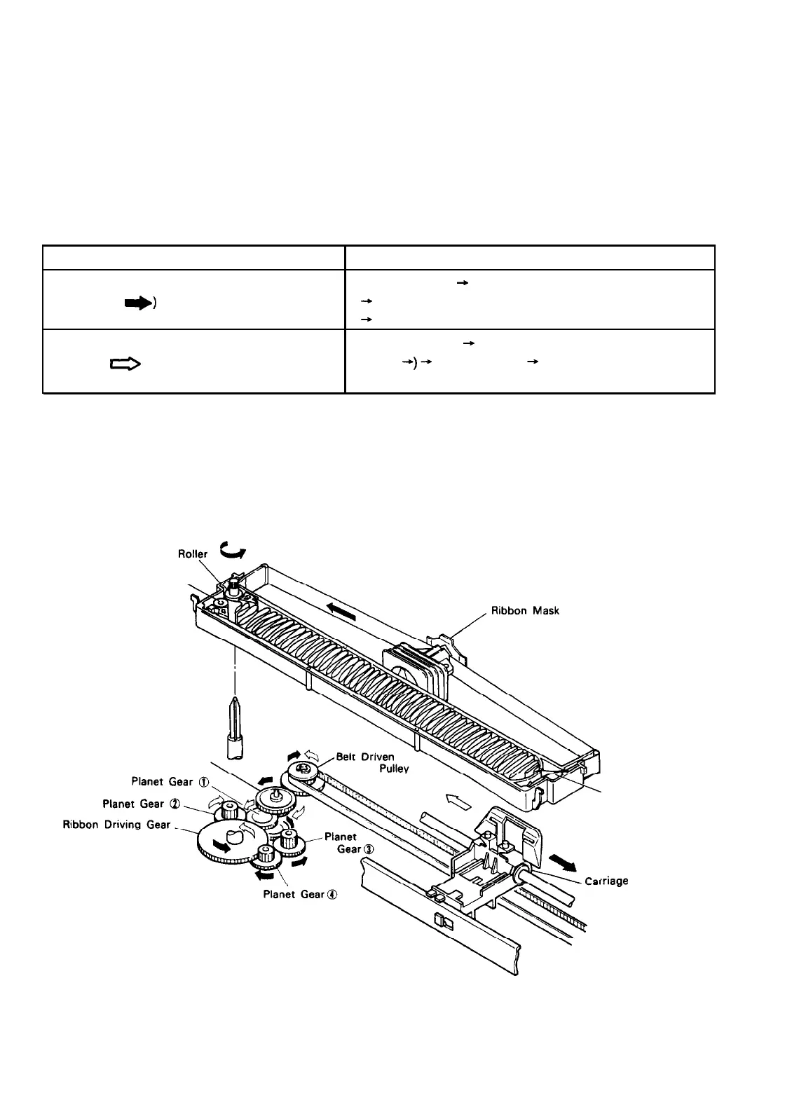
2.3.10 RIBBON-FEED MECHANISM
The ribbon-feed mechanism consists of the ribbon cartridge and the ribbon-feed section. The ribbon-driving
gear always is driven counterclockwise (regardless of the timing-belt direction) via the gear trains shown
in Table 2-10.
Table 2-10. Ribbon-Feed Gear Train
Direction of Movement of Carriage
Left to right
(arrow
*)
Right to left
(arrow
0
)
Gear Train
Beltdriven pulley
-,
Platen gear
(1)
+
Platen gear (2)
+
Ribbon-driving gear
Beltdriven pulley
+
Platen gear (1)
(arrow
d)
-,
Platen gear (3)
+
Platen gear (4)
Ribbon-driving gear
Figure 2-71 shows the ribbon-feed mechanism. The inked ribbon is held in the cartridge case between the
ribbon-feed and the ribbon-pressure roller mounted on the ribbon-driving gear. The ribbon configuration is
such that the ribbon can feed endlessly. The ribbon-driving gear drives the rollers, which causes the ribbon
to be fed. To prevent ribbon slack, a ribbon-braking spring is attached at the exit of the cartridge case. A
ribbon mask is installed to prevent the ribbon from staining the paper.
Ribbon Feed
Roller
Lv
Ribbon Pressure Roller,
Ribbon Transmission Gear
Ribbon
,riage
Braking
Spring
Figure 2-71. Ribbon-Feed Mechanism
LQ-510
2-65
 Loading...


