DISASSEMBLY, ASSEMBLY, AND ADJUSTMENT
REV.-A
NOTES FOR REASSEMBLY
The following apply to E-ring reattachment:
0 When attaching a ring to the left pulley shaft, place it so that its opening faces left.
0 When attaching a ring to the right pulley shaft, place it so that its opening faces right.
0 Use tweezers to check that the attached retaining rings are firmly in place and will not move.
4.2.5.7 Removal of Home-Position Sensor
1.
Remove the carriage motor frame. Follow steps 1 to 3 of Section 4.2.5.6.
2.
Push in the notch securing the home-position sensor, and remove the sensor from the carriage motor
frame.
Home-Position Sensor
Carriage
Motor Connector
Figure 4-33. Removal of Home-Position Sensor
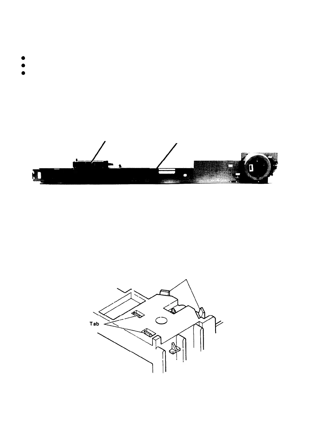
4.2.5.8 Disassembly of Ribbon-Feed Mechanism
1.
Remove the printer mechanism (refer to Section 4.2.4.2).
2.
Turn the printer mechanism upside down, and use a screwdriver to loosen the four bent tabs securing
the ribbon gear cover slightly. Only loosen the tabs slightly, and do not yet remove the cover. If the cover
is removed while the printer mechanism is upside down, the gears will scatter.
Tab
(Bottom view of printer mechanism)
Figure 4-34. Removal of Ribbon Gear Cover
3.
Turn the printer mechanism over so that it is again face up, then lift and remove the ribbon gear
cover.
4-24
LQ-510
 Loading...


