PRINCIPLES OF OPERATION
REV.-A
2.1.3 Circuit Overview
This section describes the circuitry.
2.1.3.1 Overview of the Power Supply Circuit
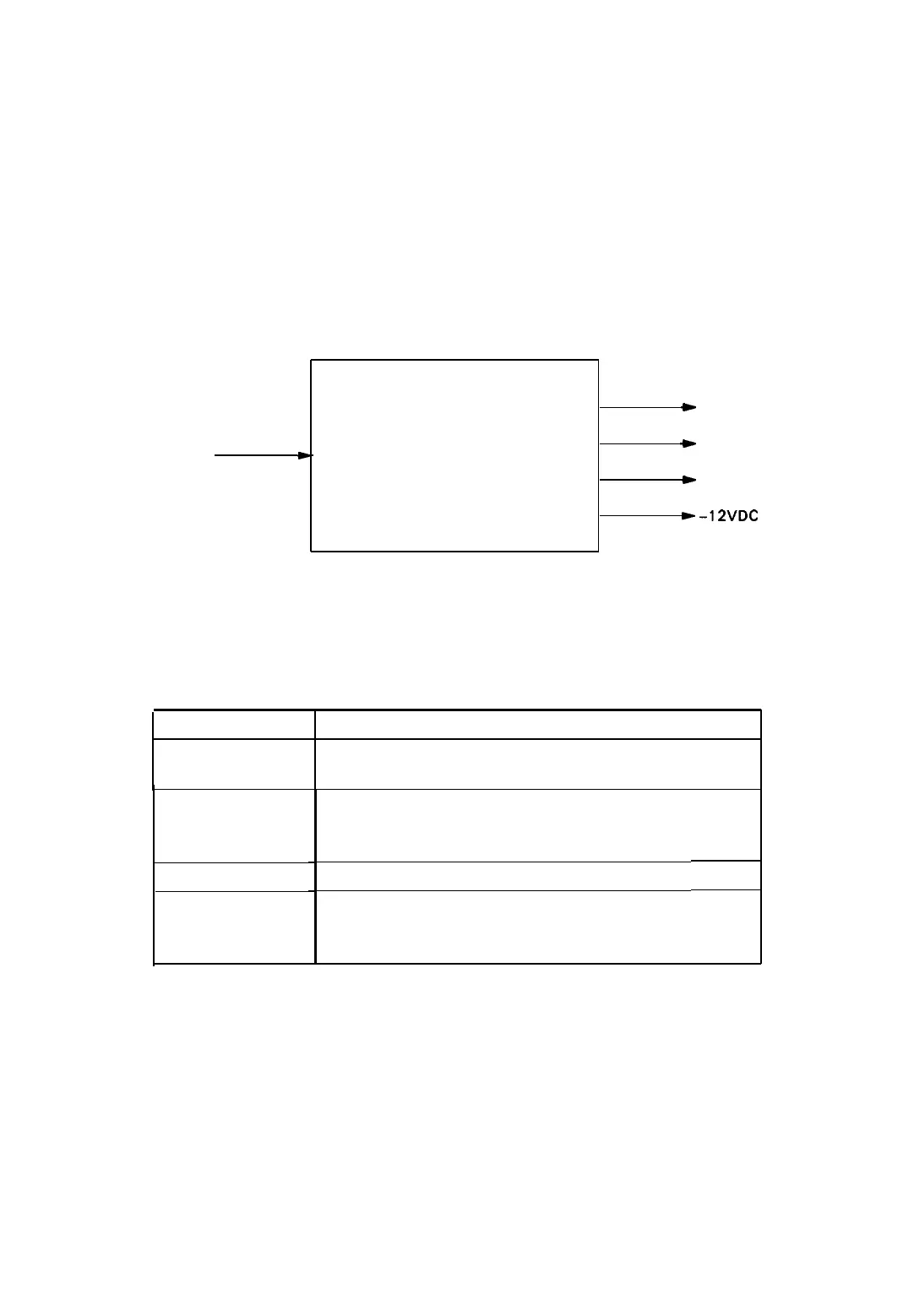
The
power circuit for this system is an SANPS(E) board. The circuit converts the AC power source to the
+ 24, + 5, and ± 12 VDC that the unit requires.
To SAMA Board
+
+24VDC
AC IN
SANPS (120V Ver)
*
+5VDC
m
SANPSE (220/24OV Ver)
(12OVAC or
220/240VAC)
)
+12VDC
b-12VDC
Figure 2-14. Overview of Power Supply Circuit Operation
Table 2-2. Power Supply Applications
Voltage
+5v
Application
Logic circuit
Paper-feed motor holding voltage, etc.
+24 V
±12 v
VX
Carriage motor drive voltage
Paper-feed motor drive voltage
Printhead drive voltage
Optional I/F voltage
Reset circuit
Printhead data signal pull-up voltage
Paper-feed motor phase data signal pull-up voltage
NOTE:
The voltage Vx is generated on the SAMA board using the + 5 V power supply.
2-10
LQ-510
 Loading...


