REV.-A
PRINCIPLES OF OPERATION
2.2 OPERATION OF THE POWER SUPPLY CIRCUIT
The power circuit used in the printer is either a 120 V SANPS board for the U.S., Taiwan, and the Middle
East or a 220/240 V SANPSE board (for Europe, Asia, etc.). The basic operation of both boards is the same,
however, and they are treated as one in this manual.
2.2.1 POWER SUPPLY CIRCUIT BLOCK DIAGRAM
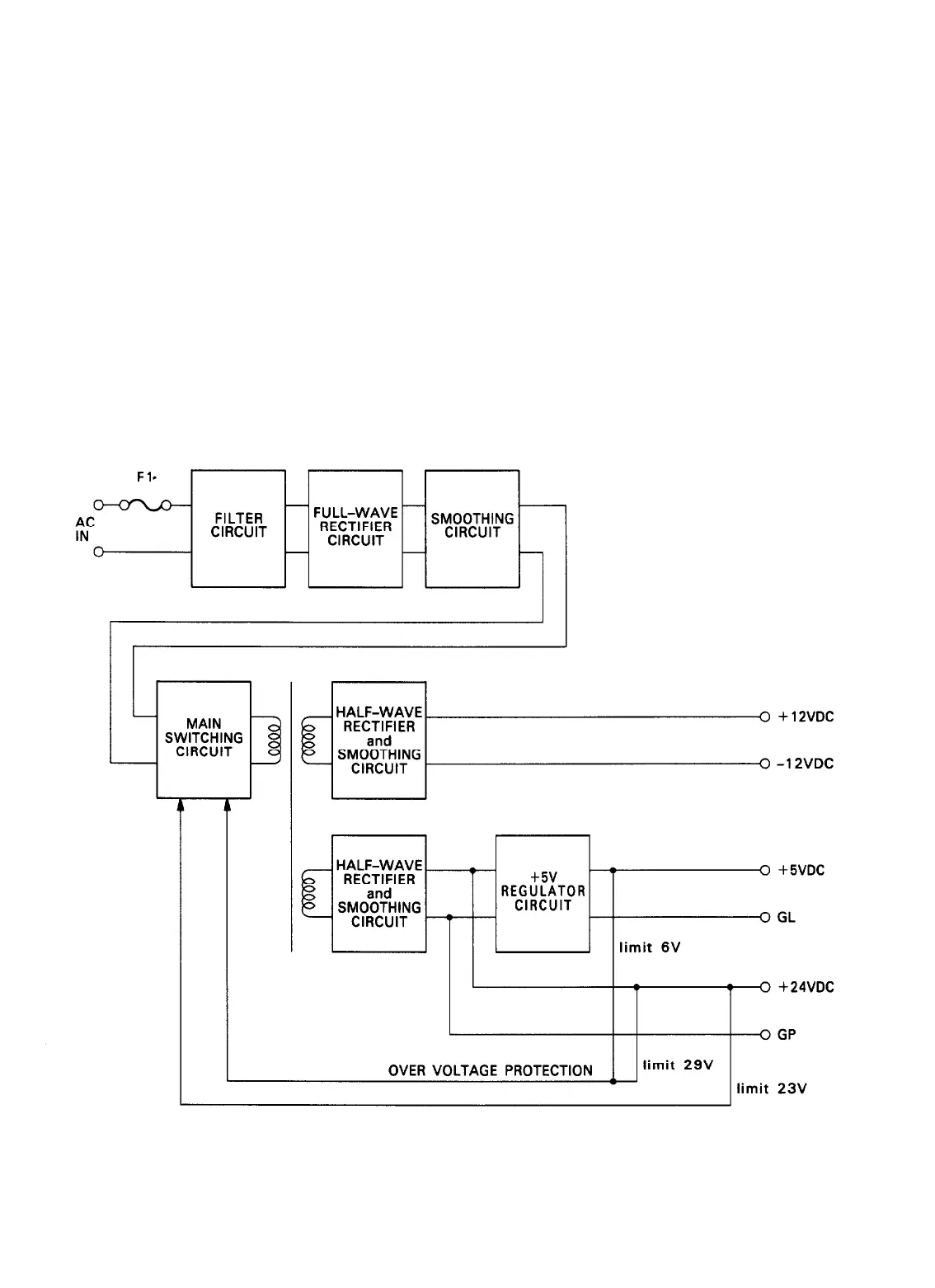
Figure 2-18 shows the power supply circuit block diagram. The SANPS(E) board uses a forward-convertor
type switching regulator circuit, and outputs + 5, + 24, and + 12 VDC.
The incoming AC power passes first through a noise filter, then through a full-wave rectifying circuit. The
power then passes into the main switching circuit, which outputs + 24 V and ± 12 VDC. Stabilization is pro-
vided by an over-voltage limiting circuit located on the 24 V line, which feeds back to the main switching
circuit. The 24 V line is also used to generate the 5 V output.
OVER VOLTAGE PROTECTION
Figure 2-16. Power Supply Circuit Block Diagram
LQ-510
2-13
 Loading...


