PRINCIPLES OF OPERATION
REV.-A
Module Installation or Removal
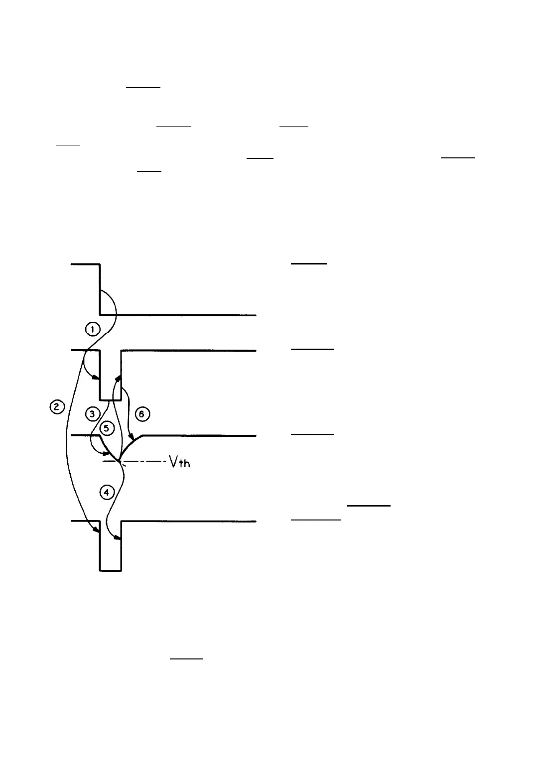
Figure 2-37 shows the RESET pulse-generation process that occurs when
a
ROM cartridge is mounted. The
bracketed numbers below correspond to the circled numbers in the figure. After the ROM cartridge is mounted,
the LOW signal flows into the CAR terminal of gate array (7A),
a
LOW signal is correspondingly output from
the DISC terminal ( 1 ), and RESET is output from the ROUT terminal ( 2 ).
As the DISC terminal goes LOW, capacitor C19 is discharged with a time constant R67 x C19 ( 3 ). When
the discharge of C19 reduces the potential at the THLD terminal to threshold voltage Vth, the RESET signal
is canceled 4 , and the DISC terminal goes HIGH ( 5 ). After the DISC terminal goes HIGH, Vx voltage
discharges C19 at time constant R40 x C19 ( 6 ).
CAR
Terminal
DISC
Terminal
THLD
Terminal
ROUT Terminal
RESET Signal
Figure 2-37. RESET Pulse Oscillation Process (Module Mounted)
2-30
LQ-510
 Loading...


