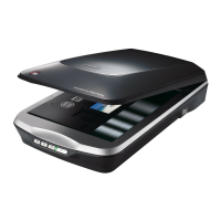
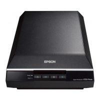
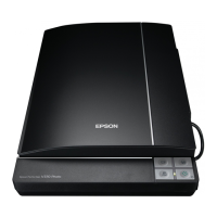
EPSON Perfection V500 Photo Revision A
DISASSEMBLY / ASSEMBLY Disassembly Procedure 30
4.2 Disassembly Procedure
This section illustrates how to remove the main components of this product. Unless otherwise specified, the reassembly procedure is the reverse of the disassembly procedure. For
additional assembly illustrations, refer to the exploded diagrams in the Appendix.
The following flowchart shows the disassembly procedure step-by-step, and the section and page number where the procedure is described.
Figure 4-1. Disassembly Flowchart
Start
Removing the TPU Unit(P.31)
Removing the Upper
Housing(P.32)
Removing the Carriage
Unit(P.33)
Removing the Panel Board(P.35) Removing the Main Board(P.36)
Removing the Driven Pulley, Driven
Pulley Spring, and the Driven Pulley
Holder Assy.(P.40)
Removing the Power
Switch(P.38)
Removing the CR Motor Unit, Motor
Timing Belt, and the CR Timing
Belt(P.41)
Removing the Panel FFC(P.39)
Removing TPU Lower
Housing(P.43)
Removing the TPU Carriage
Unit(P.46)
Removing the DRV Board(P.46) Removing the Hinge Assy.(P.44)
Removing the Sensor
Board(P.44)
Removing the SUB-C Board,
LM-B Board(P.48)
Removing the TPU CR
Motor(P.50)
Removing the TPU Unit
Cable(P.45)
Since a prototype was used to illustrate these disassembly and
reassembly procedures, the appearance of some parts may differ
from those on actual product. The procedures themselves,
however, are accurate for the retail model.
 Loading...


