26
2. Align the 3-axis adjustment unit with the slide plate’s alignment mark.
If the 3-axis adjustment unit is not aligned, loosen the M4 x 12 mm hexagon socket head cap bolt ( )
and correct the alignment ( ). Then, tighten the M4 × 12 mm hexagon socket head cap bolt.
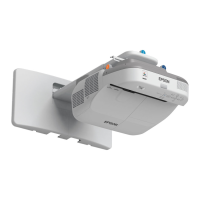
3. Attach the 3-axis adjustment unit and slide plate to the projector.
Attach the 3-axis adjustment unit and slide plate to the projector using the M4 × 12 mm hexagon socket
head cap bolts (×4) supplied.
 Loading...

