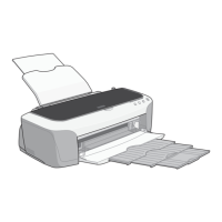
EPSON Stylus PHOTO 2100/2200 Revision B
DISASSEMBLY AND ASSEMBLY Disassembly 163
5. Remove the one screw 11) C.B.P 2.5×5 (1.5±0.25kgf.cm) that secures the PF
Encoder Sensor, and remove the PF Encoder Sensor.
Figure 4-94. Removing the PF Encoder Sensor
4.2.12.4 Removing the CD-R Sensor
1. Remove the Front Frame. (Refer to Steps 1 to 7 in 4.2.5.)
2. Release the two hooks that secure the CD-R Sensor, and remove the CD-R Sensor.
Figure 4-96. Removing the CD-R Sensor
" When reinstalling the PF Encoder Sensor, insert the two cutouts
and then push the hook in.
Refer to Figure 4-95, "Reinstalling the PF Encoder Sensor".
" Pass the FFC of the PF Encoder Sensor through under the Arm
of the PF Encoder Sensor Frame.
Refer to Figure 4-95, "Reinstalling the PF Encoder Sensor".
Figure 4-95. Reinstalling the PF Encoder Sensor
PF Encoder
Sensor
C.B.P 2.5×5
Arm
FFC
Cutouts
" When connecting the Connector Cable to the CD-R Sensor, use
tweezers and connect correctly.
Refer to Figure 4-47, "Removing the Front Frame".
" Connect the CD-R Sensor Connector Cable with the Tie Wraps
of the Front Frame correctly.
Refer to Figure 4-47, "Removing the Front Frame".
CD-R Sensor
Hooks

 Loading...


