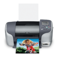
EPSON Stylus Photo 925 Revision A
Operating Principles Electrical Circuit Operating Principles 43
2.2.2.1 Main Elements
Following table provides the description of main element functions on the C475 main
board.
Table 2-10.Main Elements (Printer section)
IC Location Function
CPU-ASIC 2in1
E01A27CA
IC11 16bit CPU mounted on the MAIN board is driven by
clock frequency 24MHz and controls the printer
PROM IC9 • Capacity 4/8/16MB, Bus= 16 bit
• Program for CPU or Program +CG
DRAM IC10 • Bus= 16 bit, 4Mbit DRAM
• Various buffers and work area
RTC9822
(Reset function,
RTC, EEPROM
compound IC)
IC8 EEPROM section
• Default value setting
• Parameter backup
RESET section
• For +3.3V; reset when +2.5V is detected
• For +5V; reset when +4.2 is detected
• For +42V; reset when +36 is detected
TIMER section
• Electric double layer capacitor (0.33F) is used.
Common Driver IC18 Head drive control HIC
• Generates head common voltage.
Motor Driver IC13 CR motor drive IC
Motor Driver IC14 PF motor drive IC
Motor Driver IC12 ASF motor drive IC
Motor Driver IC7 Cutter motor drive IC
Table 2-11.Main Elements (Printer section)
IC Location Function
CPU
V833
IC1 • USB storage class target
• Control of various cards
• Image processing
• Operating frequency: 60MHz
ASIC
E09A40BA
IC2 • Package:256 pin PBGA
• Operating frequency:60MHz and 48MHz
• Data communication with the printer section
• Start and finish of DMA by MWPACKU
• Switch status reading from LCD panel
PCMCIA(CF)
Socket Power
Controller
MAX1602
IC16 • Package: 16pinS.O Package
Flash ROM
MBM29PL160TD
-PFTN
IC3 • Capacity:16/8Mbit Bus=16bit
•Program
SDRAM
K4S641632D
IC4/IC5 • Capacity:64Mbit (1M x 16bit x 4bank)ÅCBus=16bit
• System memory
USB HUB IC
TUSB2036VF
(TI)
IC6 • Self power/pass power mode
• Applicable to full speed/low speed related to all
Down Stream ports
• Applicable to the suspend/resume operation
• Suspend/status output
USB HOST
Controller
ISP1161
IC19 • Package: LQFP64 Bus=16 bit
• External USB storage control

 Loading...


