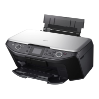
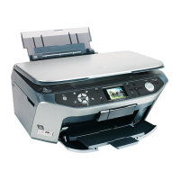
EPSON Stylus Photo RX585/RX595/RX610 Revision B
Disassembly and Assembly Removal of Exterior Parts 65
4.2.2 Scanner Unit
1. Remove the Panel Assy (p.63)
2. Remove the Paper Support.
3. Open the Scanner Unit, slide the Scanner Cable Cover toward the front and
remove it from the Middle Housing. (Fig. 4-10)
4. Release the following FFCs and cables from the Middle Board, and disconnect
them from the Main Board. (Fig. 4-11)
5. Remove the screw securing the grand wire of the scanner.
6. Close the Scanner Unit, and remove the screws (x2) in the rear. (Fig. 4-12)
7. Remove the Scanner Unit, kept in the open position, from the printer body.
Figure 4-10. Removing the Scanner Cable Cover
Figure 4-11. Disconnecting the cables and FFC (Scanner Unit)
Figure 4-12. Removing the Scanner Unit
Figure 4-13. Installing the Scanner Unit
CN No. Color Connected to Remarks
CN17 White CR Motor 2-pin (With a ferrite core)
CN19 (FFC) CIS Unit 14-pin (With a ferrite core)
CN20 White CR Encoder 4-pin
The harness for the Scanner CR Motor (CN17) and that for the
CR Motor (CN14) are provided with the same 2-pin white
connector. Take care not to confuse them when connecting the
connectors to the Main Board.
Route the FFCs and cables of the scanner as shown in the
figure.
(Fig. 4-13)
When installing the scanner cable, take care that no part of the
cable is positioned outside the cover. (Fig. 4-10)
Scanner Cable Cover
Slide it toward the front for removal
No part of cable outside
Position the soldered joint up
and after tightening the screw,
bend the joint downward.
C.B.P-TITE 3x10
Torque : 0.6±0.1N
·m
Ferrite Core
CN17
(White)
CN20
(White)
CN19
After routing the cables,
secure them with acetate tape.
Route the cables of CN17 and
CN20 behind Head FFC.
Head FFC
C.B.P-TITE 3x10 (x2)
Torque : 0.6±0.1N
·m
Grounding wire
under CN19
Place the
ferrite cores
here
Route the cables on the front side as viewed
from here, ensure the adequacy of the cable
length by pushing the cables into the space
at the bottom corner, and route them
through the grooves in the Middle Housing.
Scanner Unit
Middle Housing
Push them in
CN17
(Left end, 2-pin)
Double-stick
tape x3
CN19

 Loading...


