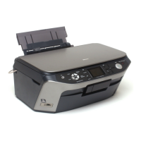
EPSON Stylus PHOTO RX640/650 Revision A
Operating Principles Operating Principles of Electric Circuitry 18
2.2 Operating Principles of Electric Circuitry
2.2.1 Overview
The major circuit boards of Stylus PHOTO RX640/650 are as follows:
Main Board: C608MAIN
Power Supply Board: C608PSB/C608PSE
Panel Board: C608PNL and C608PNL-B
CCD Unit Board (Scanner): C608ISN
USB I/F Board : I/F Board Assembly
2.2.2 Features
High-Speed SPC is realized without HUB, thanks to employment of USB 2.0
multi-end point.
An SOC incorporating the printer controller, scanner controller, PT controller
and CPU Super Macro is realized.
Only one CPU (SH2A by RENESAS) controls the printer, scanner and PT
section.
Equipped with one 64-Mbit Flash ROM (with 16-bit bus width) and one 32-
Mbit Flash ROM (with 16-bit bus width).
(Flash ROM or MASK ROM is mounted)
Equipped with one 256-Mbit SDRAM (16-bit bus width) for ASIC local
buses, and one 256-Mbit SDRAM (16-bit bus width) for CPU bus.
Low cost of logic power supply and motor drive is realized by employment of
motor drivers with built-in power supply.
The band width is ensured by setting the operating frequency of the local
SDRAM of SOC at 96 MHz.
High-speed processing is ensured because all the processing from scanning to
binarization, Microweave, and image buffer generation is carried out inside
the SOC, without via the CPU bus.
The size of the MW buffer is reduced to 1/3 of the conventional size by
employment of UBEC (Ultra Block Encode).
Equipped with a color LCD (2.5-inch low-temperature poly-silicon TFT
liquid crystal) as a standard feature.
Power consumption is suppressed by executing the following actions at
transition to the power save mode.
• Lowering the supply voltage for main power
• Cutting off the photo-electric current of the photo sensor
• Stopping the motor drive circuit
• Stopping the UDL clock inside the ASIC
• Entering the CPU core low consumption mode
• High efficiency power supply circuit
• Stopping excitation of the printer motor
• Stopping the head drive circuit
• Turning off the CCD scanner power supply and stopping the excitation of the
scanner motor
• Turning off the preview monitor
2.2.3 Circuit Board Constitution
Table 2-5. Circuit Board Constitution
Circuit Board Description
Main
Board
System section
Logic circuits (ASIC incorporated in the CPU core, Flash ROM
x 2, and SDRAM x 2)
Interface circuit (USB 2.0, USB 1.1 Host)
RTC circuit
Color LCD interface
Panel interface
IrDA circuit
Power Supply
section
Regulator circuit
Power switch circuit
Overvoltage protection circuit
Printer section
Motor control and drive circuits (PF, CR)
Head control and drive circuit
Sensor circuits (PE, PF, PW, APG, CDR 1 and 2)
Card ASIC section
Logic circuit (ASIC)
Card power supply control circuit
Scanner section
Scanner interface circuit
Motor control and drive circuit (Scanner)
Scanner HP detection interface circuit
TPU interface circuit
Panel Board
Power switch circuit
Switching circuit
LED circuit
ISN Board
CCD control and A/D conversion circuit
Optical sensor circuit
LCD Board
LCD control circuit
LCD module
SDRAM
 Loading...