17
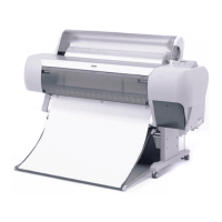
Figure 4-1. Directional View of the Printer
C A U T I O N
n When replacing connector wires, be careful to replace the entire
length of the wire exactly as you found it; rubbing against edges
or moving parts can cause noise in the wires.
n The cutter blade is very hard and can damage or scratch printer
parts, and it can also be chipped or damaged. Be careful when
handling or replacing the cutter.
n If you have to loosen a screw that has blue screw-lock applied to
its head, make sure you apply blue screw-lock again when
reassembling.
n When tight the screw that has no tightening torque value, secure
it not to make screw loosen.
C H E C K
P O I N T
n If you find it is necessary to perform service on a part not
described in this chapter, be sure to check the after-service parts
situation before beginning the service.
n If necessary (i.e. when transporting the printer) use the above
mentioned mode to drain ink, install the discharge cartridges (P/
N:1060627), and then perform an initial ink charge with the
fluid. Enter the transportation mode again to remove the fluid
(user can do) and then perform initial ink charge with ink.
n The directional instructions in this chapter are given as if viewing
the printer from the front. See the illustration below.
Top
Bottom
Rear
Front
R
L
 Loading...


