Innova 1999
B. AMMETER
WARNING: Make sure the maximum capacity of your charging
system does not exceed the ammeter's dialface capabilities.
NOTE: We strongly recommend professional installation or
assistance when installing an ammeter.
1. Determine routing for ammeter wiring. Use an existing firewall
grommet, or drill a hole through firewall to accommodate wires.
Install a rubber grommet (purchased separately) in hole, use
shrink tubing, or wrap with electrical tape to protect wiring from
chaffing or other damage.
NOTE: Ammeter wiring must be purchased separately. Use 10
AWG wire minimum.
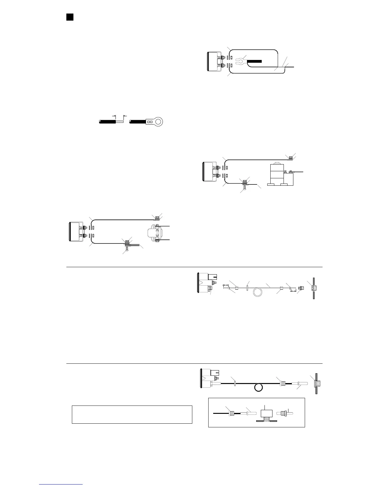
2. Crimp or solder ring terminals (purchased separately) on ammeter
positive (+) and negative (–) wires. Connect wires to ammeter using
two nuts and flat washers. TIGHTEN NUTS SECURELY.
PROPERLY INSULATE ALL CONNECTIONS.
NOTE: This is an "in–line" attachment gauge. NEVER GROUND
GAUGE STUDS OR WIRES.
3. Route wiring through grommet in firewall.
4. Connect ammeter wiring to charging system:
■ For magnetic starter switch systems (Ford/Chrysler), see Wiring
Diagram A. Remove nut and washer from starter solenoid switch
battery connection post "A". Remove all wires except wire going
to battery. Connect ammeter positive (+) lead to post "A";
reinstall washer and nut. Connect ammeter negative (–) wire to
wire(s) removed from post "A" using screw, lockwasher, and nut
(purchased separately).
■ Insulate terminal lug connection using shrink tubing or
electrical tape to prevent shorting.
+
–
BOTTOM
VIEW
NUT
WASHER
TERMINAL
LUG
TO
BATTERY
TO
STARTER
NUT
WASHER
TERMINAL
LUG
SCREW
EXISTING WIRE(S) REMOVED FROM
STARTER SOLENOID SWITCH TERMINAL "A"
AMMETER
NEGATIVE (
–
)
WIRE
AMMETER
POSITIVE (
+
)
WIRE
AMMETER CONNECTION DIAGRAM A (FORD/CHRYSLER)
STARTER
SOLENOID
SWITCH
"A"
+
–
■ For voltage regulator/horn relay circuit systems (GM/Chrysler)
see Wiring Diagram B. Splice ammeter positive (+) and
negative (–) wires into wire from battery positive (+) to voltage
regulator.
■ For most starter solenoid circuits (GM/AMC), see Wiring
Diagram C. Remove nut and washer from starter solenoid
battery connection post "A". Remove all wires except wire
going to battery. Connect ammeter positive (+) wire to post
"A"; reinstall washer and nut. Connect ammeter negative (–)
wire to wires removed from post "A" using screw, lockwasher,
and nut (purchased separately).
■ Insulate terminal lug connection using shrink tubing or
electrical tape to prevent shorting.
5. Reconnect negative (–) battery cable. Turn on headlights and
observe ammeter. Ammeter should indicate "–". If ammeter
reads backwards, reverse the positive (+) and negative (–)
connections. If ammeter fails to read, turn off headlights and
recheck connections.
NOTE: If none of the diagrams matches your vehicle's system,
consult your vehicle's service manual or a qualified mechanic.
+
–
BOTTOM
VIEW
AMMETER
NEGATIVE (
–
)
WIRE
AMMETER
POSITIVE (
+
)
WIRE
AMMETER CONNECTION DIAGRAM B (GM/CHRYSLER)
BATTERY POSITIVE
(+) CABLE
TO
STARTER
SPLICE
SPLICE
CUT AND
REMOVE
TO VOLTAGE
REGULATOR
BATTERY
TERMINAL
+
–
X
+
–
BOTTOM
VIEW
NUT
WASHER
TERMINAL
LUG
TO
BATTERY
NUT
WASHER
TERMINAL
LUG
SCREW
EXISTING WIRES REMOVED FROM
STARTER SOLENOID
AMMETER
NEGATIVE (
–
)
WIRE
AMMETER
POSITIVE (
+
)
WIRE
AMMETER CONNECTION DIAGRAM C (GM/AMC)
STARTER
SOLENOID
+
–
"A"
GAUGE CONNECTION (Continued)
6
1/4"
TRIM INSULATION INSTALL TERMINAL
C. MECHANICAL OIL PRESSURE
NOTE: Before installation, use shop cloths and drip pans to protect
vehicle interior from potential leaks.
1. Determine routing for nylon tubing. Use an existing firewall
grommet, or drill a 3/8" (9.5 mm) diameter hole through firewall to
accommodate nylon tubing. Install a rubber grommet (purchased
separately) in hole, use shrink tubing, or wrap with electrical tape to
protect nylon tubing from chaffing or other damage.
NOTE: Some gauges (i.e. #6520) require tubing kit #6801 for
installation.
2. Connect nylon tubing to gauge using compression sleeve and
compression nut. Tighten compression nut until tubing is secure.
3. Route nylon tubing through grommet in firewall.
4. If necessary, install adapter in appropriate pressure port on
engine.
5. Connect nylon tubing to pressure port adapter using tube
connector, compression sleeve and compression nut. Tighten
compression nut until tubing is secure.
6. Secure tubing along its route to prevent damage from sharp
edges, moving parts or hot engine components.
7. Reconnect negative (–) battery cable. Start and run engine for
approximately 30 seconds. Turn off engine and check gauge
installation for leaks. Tighten or reseal joints as needed and
retest.
OPTIONAL
GROMMET
COMPRESSION
SLEEVE
COMPRESSION
NUT
COMPRESSION
NUT
COMPRESSION
SLEEVE
TUBE
CONNECTOR
*
OPTIONAL
ADAPTER*
*
USE TEFLON SEALING TAPE ON NOTED THREAD JOINTS.
NYLON
TUBING
ENGINE
BLOCK
GAUGE
PORT
*
1/8"
1/8"
D. MECHANICAL TEMPERATURE
1. Determine routing for temperature sensor. Use an existing
firewall grommet, or drill a 7/8" (22 mm) hole through firewall to
accommodate capillary tube with sensor. Install a rubber
grommet (purchased separately) in hole, use shrink tubing, or
wrap with electrical tape to protect capillary tube from chaffing or
other damage.
2. Route capillary tube through grommet in firewall.
3. Remove existing temperature sensor. Install adapter in sensor
hole and tighten securely. Insert temperature sensor in adapter
and tighten sensor nut securely. DO NOT ROTATE SENSOR OR
CAPILLARY TUBE WHILE TIGHTENING NUT OR CAPILLARY
TUBE MAY BE DAMAGED.
4. Secure capillary tube along its route to prevent damage from
sharp edges, moving parts or hot engine components. DO NOT
CRIMP THE CAPILLARY TUBE.
5. Reconnect negative (–) battery cable. Start and run engine and
check gauge installation for leaks. Tighten or reseal joints as
needed and retest.
NOTE: An adapter must be used to seat the sensor.
OPTIONAL
GROMMET
SENSOR
NUT
*
TEMPERATURE
SENSOR
ENGINE
BLOCK
OPTIONAL
ADAPTER
*
*
USE TEFLON SEALING TAPE ON NOTED THREAD JOINTS.
GAUGE
TEMPERATURE
SENSOR
ENGINE
BLOCK
OPTIONAL
TEE FITTING
*
EXISTING
TEMPERATURE
SENSOR/SWITCH
ALTERNATE CONNECTION DIAGRAM
SENSOR
NUT
*
NOTE: The capillary tube is under pressure and filled with ether.
NEVER CUT THE TUBE OR ATTEMPT TO REMOVE FROM
GAUGE PORT.
 Loading...