DESCRIPTION 5 (6)
Uppgjord (även faktaansvarig om annan) - Prepared (also subject responsible if other) Nr .- No.
KI/ECS/S/MP Sven-Erik Wahl KI/ECS/S/M-98:0957
Dokansv/Godk - Doc respons/Approved Kontr. - Checked Datum - Date Rev. File
KI/ECS/S/MPC (Johan Gentz) 1998-11-13 A
3.4 255-CHANNEL BOARD
The 255-channel board has the necessary circuit to enable the
controlling of 255 channels. It is installed inside the radiounit and the
backplane is equipped with an optional channel-selector.
4 PROGRAMMING
The radio unit is fully microprocessor controlled, Parameters such as
operational frequencies and mode of operation are stored in
EEPROM. The content of the EEPROM is easily changed with a
special software. All signaling are controlled by the microprocessor
based linepanels. The data in the linepanel can also easily be
changed.
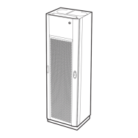
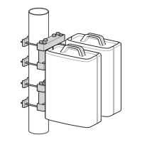
5 RADIO CABINET
The base station is housed in a 19” cabinet intended for rack or wall
mounting with special brackets. The cabinet houses the radio unit, a
duplex filter and the line interface. Each base/repeater station is fitted
with a fan that starts when the transmitter is keyed. To enable easy
removal for servicing, the radio unit is mounted in a cassette inside
the cabinet housing.
All internal interconnections between the radio unit and the line
interface slot are made via a back plane board. On the back plane,
switches for channel selection and different AF straps are found.
All connections are made with connectors on the rear end of the
cabinet. The line is connected to the base station through an external
line connection. The antenna is connected to the cabinet with a N-
type connector.
The base stations is powered by an 13,2 VDC external power supply.
 Loading...