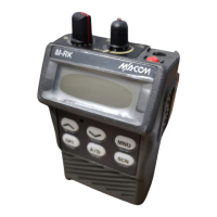
LED Flex Assembly (M-RK I)
The LED flex board is composed of the following items:
• LED (DS1, DS2, DS3)
• Volume Control with ON/OFF Switch (R8)
• Channel Select Switch (S1)
• Microphone (MK1)
• Speaker (LS1)
LCD/KB Flex Assembly (M-RK II & Scan)
The LCD/KB flex board composed of the following
items:
• Display Processor (U1)
• LCD Drive IC (U2)
• LCD (DS6)
• Backlighting Circuit (Q1 and DS1 - DS5)
• Volume Control with ON/OFF Switch (R8)
• Channel Select Switch (S1)
• Microphone (MK1)
• Speaker (LS1)
The LCD driver converts data from the Display proces-
sor into a signal which can drive the LCD display. The LCD
display is equipped with 16 character dot matrix and 15
ICONs. Microprocessor signals drive LCD driver which
turns the LCD on. Also, this board has a backlighting circuit.
Keypad (M-RK II & Scan)
There are 15 key switches (keypads) on the System
model of M-RK II. The keypads consist of flexible cable and
rubber contacts, and each connect through cable to the mi-
crocomputer. There are 6 key switches on the M-RK II Scan
model.
UDC
The UDC (located on the side of the radio housing) al-
lows various kinds of external equipment connections to be
made. External equipment connecting signals are as follows:
• EXT MIC IN •
EXT EMR IN
• 12V IN •
MUTE OUT
• AUDIO OUT •
EXT PTT IN
• SWA + OUT • GND
• UDC SENS IN • TX DATA IN
•
T/R OUT • RX DATA OUT
The radio control microprocessor senses the value of
voltage at the UDC sens line and switched the appropriate
audio circuits to provide proper radio/accessory operation.
The UDC voltage is set by the resistor within the UDC.
Figure 15 - Synthesizer
LBI-38735
17

 Loading...