MAINTENANCE
This Maintenance section provides information on ad-
justment of the radio (transmit, receive, and synthesizer),
preventive maintenance and a disassembly procedure. Infor-
mation is also provided for removing and replacing chip
component and module replacement. The Service Section,
listed in the table of contents, provides a more complete set
of alignment procedures for the radio plus a detailed trou-
bleshooting procedure.
INITIAL ADJUSTMENT
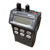
The M-RK radio personality is programmed using an
IBM compatible personal computer and programming soft-
ware. The procedure is described in the applicable program-
ming manual.
After the radio personality has been programmed, the fol-
lowing adjustments should be made by a qualified electron-
ics technician.
Transmit Circuit Alignment
The transmit circuit is factory turned and should not re-
quire any readjustment. The frequency and modulation
should be measured and recorded for future reference.
Receive Circuit
No initial adjustments to the receive circuit are required.
Synthesizer Circuit
No initial adjustments to the synthesizer are required.
PREVENTIVE MAINTENANCE
To ensure a high operating efficiency and to prevent me-
chanical and electrical failures, routine checks should be per-
formed on all mechanical and electrical parts at regular
intervals. Preventive maintenance should include the follow-
ing checks.
Antenna
The antenna and antenna contact should be kept clean
and free from dirt or corrosion. If the antenna or contact
should become dirty or corroded, loss of radiation and a
weak signal will result.
Mechanical Inspection
Since portable radio units are subject to shock and vibra-
tion, check, for loose plugs, nuts, screws and other parts to
make sure that nothing is working loose.
Alignment
The transmit and receive circuit meter readings should be
checked periodically and the alignment "touched up" when
necessary. Refer to the applicable alignment procedure and
troubleshooting sheet (found in the Service Section) for typi-
cal voltage readings.
Frequency Check
Check transmit frequency and deviation. Normally, these
checks are made when the unit is first put into operation.
They should be repeated after the first month of operation,
then again one time each year.
DISASSEMBLY
Procedures to access the Radio Board Assy (transmit, re-
ceive, and synthesizer circuits) or Control Board Assy for
servicing are explained in the following paragraphs.
• TORX screwdriver (T-8) . . . . . . . . . . . . . . 1
• Screwdriver (M2) . . . . . . . . . . . . . . . . . . 1
• Pencil type soldering iron (25-40 watts)
with a fine tip. . . . . . . . . . . . . . . . . . . . . 1
REPLACEMENT
The major components of the M-RK Personal Radio are
the PA, LPF/DC/T/R SW, VCO (Voltage-Controlled Oscilla-
tor), and the VCTCXO (Reference Oscillator). These are
very reliable devices and will not normally need to be re-
placed. Before replacing any of these modules, always check
out the associated circuitry carefully.
To remove any of these major components, refer to the
applicated replacement procedure found in the Service Sec-
tion.
Always remove the battery pack before removing
any component board to avoid blowing the fuse.
CAUTION
LBI-38735
18
 Loading...