• Programmable Talkaround Capability -- The ability to
switch the transmit frequency from a repeater
frequency to a direct communications frequency.
• Channel-Busy Lock Out -- Personality information
includes the capability to prevent the transmitter from
operating on a channel where carrier activity is
present. The channel busy indicator (BSY) is active
during this time.
Physically an M-RK radio consists of three main printed
wire board assemblies and a battery pack as follows:
a. A printed wire board specially shielded with zinc al-
loy on which the radio assembly (transmit/re-
ceive/synthesizer) is assembled.
b. A Control board containing the microprocessor.
c. A LCD/KB flex wire board with display processor,
rotary switch, AF volume with switch.
d. A battery pack that fits the M-RK main unit.
e. Lightweight plastic front and back housing.
RADIO ASSEMBLY
TRANSMIT CIRCUIT
The transmit circuit consists of four major circuits as fol-
lows:
a. Wide Band Amplifier -- Amplifies the signal from the
frequency synthesizer.
b. Wide Band Power Amplifier -- Amplifies the output
signal of the amplifier to the desired output level for
transmission (a gain of 38.5 dB).
c. Wide Band Power Control Circuits -- Can reduce the
transmitter output level by 10 dB.
d. LPF, DC, Switch Hybrid Module -- Consists of LPF
and directional coupler and Tx/Rx switch.
The transmitter completely covers the band within the
split. No adjustments are needed except for the RF power
control voltage from the controller.
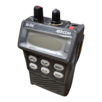
Figure 1 - M-RK I Controls and Accessories
Figure 2 - M-RK II & Scan Controls and Accessories
LBI-38735
7
 Loading...