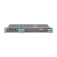
MINI-LINK TN R3 ETSI
The following loops on the near-end Radio Terminal are supported in order to
find out if the MMU or RAU is faulty.
IF Loop
In the MMU the traffic signal to be transmitted is, after being
modulated, mixed with the frequency of a local oscillator and
looped back for demodulation (on the receiving side).
RF Loop In the RAU a fraction of the RF signal transmitted is shifted in
frequency and looped back to the receiving side.
9971
MMU MMURAURAU
Rx LoopIF Loop RF Loop
Near-end Far-end
Note: For MMU2 E/F, also a Local Loop
is available at the Far-end MMU.
Figure 86 Radio Terminal loops
The AAU supports a Loop Back function described in Section 3.7.2.2 on page
41.
6.1.3 User Input/Output
The NPU1 B provides three User Input and three User Output ports. The NPU3
provides two User Output ports.
The User Input ports can be used to connect user alarms to the MINI-LINK
management system. Applications like fire alarms, burglar alarms and low
power indicator are easily implemented using these input ports. The User Input
ports can be configured to be normally open or normally closed.
User Output ports can be used to export summary alarms of the accumulated
severity in the NE to other equipment’s supervision system. The User Output
ports can be controlled by the operator or triggered by one or several alarm
severities.
The setup of the User Input/Output is done in the EEM.
1
08
4
/1555-CSH 109 32/1-V1 Uen B 2007-09-14

 Loading...