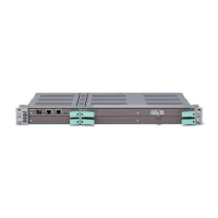
Basic Node
9958
NPU3
+
_
+
_
Redundant Power
Supply
–48 V DC or
+24 V DC
Figure 12 Power supply f or AMM 2p B
3.2.1.2 Cooling
AMM 2p and AMM 2p B can be used with or without forced air-cooling,
depending on the configuration. Forced air-cooling is provided by FAU4, placed
vertically inside the AMM. FAU4 holds three internal fans.
If the indoor location has other fan units, which provide sufficient cooling
through the AMM, the FAU4 can be omitted. However, air filters should be
present in the cabinet door.
Complete rules for cooling are available in MINI-LINK TN ETSI Product
Specification and the Product Catalog.
Air in
Air out
9715
02
03
02
03
MMU2 E 155
NPU3
Figure 13 Cooling airflow in AMM 2p B
The air enters at the right hand side of the AMM and exits at the left hand
side of the AMM.
3.2.2 AMM 6p B /C/D
AMM 6p B/C/D is suitable for medium-sized hub sites or prioritized small-sites
with 1+1 protection.
AMM 6p B has six full-height horizontal slots and two half-height vertical slots.
It houses one NPU1 B, one or two PFU3 and one FAU2, see Figure 14 on
page 14.
AMM 6p C or D have four (D) or five (C) full-height horizontal slots, four (D) or
two (C) half-height horizontal slots and two half-height vertical slots. They
house one or two NPU3, one or two PFU3 B and one FAU2, see Figure 15 on
page 14 and Figure 16 on page 14.
13
4/1555-CSH 109 32/1-V1 Uen B 2007-09-14

 Loading...