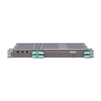
MINI-LINK TN R3 ETSI
3.4.2.2 Functional Blocks
This section describes the internal and external functions of the LTUs with E1
interfaces, based on the block diagram in Figure 29 on page 26.
6662
SPI
TDM
TDM Bus
PCI Bus
SPI Bus
Power
Power Bus
Secondary
voltages
Line
Interface
12xE1 or
16xE1
Control and
Supervision
Figure 29 Block diagram for LTU 16/1 and LTU3 12/1
3.4.2.2.1 TDM
This block interfaces the TDM bus by receiving and transmitting the traffic
(nxE1).
3.4.2.2.2 Control and Supervision
This block interfaces the PCI bus and handles control and supervision. Its main
functions are to collect alarms, control settings and tests.
The block communicates with the NPU over the PCI bus.
3.4.2.2.3 SPI
This block interfaces the SPI bus and handles equipment status. Failure is
indicated by LED’s on the front of the unit.
3.4.2.2.4 Power
This block interfaces the Power bus and provides secondary voltages for the
unit. All plug-in units have a standard power module providing electronic soft
start and short circuit protection, filter function, low voltage protection, DC/DC
converter and a pre-charge function.
2
6
4
/1555-CSH 109 32/1-V1 Uen B 2007-09-14

 Loading...