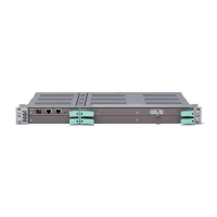
MINI-LINK TN R3 ETSI
3.7 ATM Aggregation
3.7.1 Overview
The growing demand for higher transmission capacity in access networks can
be handled by increasing the physical capacity, introducing traffic aggregation
or combining the two approaches.
Traffic aggregation in MINI-LINK TN R3 is achieved by fitting an ATM
Aggregation Unit (AAU) in the AMM. This is typically done at hub sites where
HSDPA traffic is aggregated, thus reducing the number of required E1 links in
the northbound direction. The AAU performs ATM VP/VC cross-connection
providing statistical gains.
Figure 37 on page 36 shows an example of how Virtual Paths (VP) and Virtual
Channels (VC), carried over E1s, can be cross-connected reducing the number
of required E1s.
VP/CBR
11xE1
VC/UBR+
Shared
13 Mbit/s
VC/UBR+
VP/CBR
8xE1
VC/UBR+
11.3 Mbit/s
VC/CBR
4.7 Mbit/s
VC/CBR
4.7 Mbit/s
VP/CBR
8xE1
VC/UBR+
11.7 Mbit/s
VC/CBR
4.3 Mbit/s
VC/CBR
4.3 Mbit/s
8924
MINI-LINK TN
with AAU
Figure 37 VP/VC cross-connection
Often the transmission network is used for both GSM and WCDMA traffic. The
GSM traffic is handled as ordinary TDM traffic routed in the backplane and
transported transparently through the NE while WCDMA traffic is routed to the
AAU for packet aggregation before it is routed to its destination port. WCDMA
traffic comprises both R99 standard (voice and data channel up to 384 kbit/s)
and HSDPA traffic. The largest aggregation gain is however obtained for the
HSDPA traffic, when the low priority traffic can be transported using best effort
service categories.
Figure 38 on page 37 shows how the different traffic types are routed in the
backplane.
3
6
4
/1555-CSH 109 32/1-V1 Uen B 2007-09-14

 Loading...