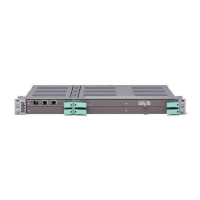
MINI-LINK TN R3 ETSI
3.9.3 MSP 1+1
The STM-1 interface supports Multiplexer Section Protection (MSP) 1+1.
This SDH protection mechanism provides both link protection and equipment
protection. Its main purpose is to provide maximum protection at the interface
between the microwave network and the optical network.
MSP 1+1 requires two LTU 155 plug-in units configured to work in an MSP 1+1
pair, delivering only one set of 63xE1 (or 21xE1) to the backplane at a time as
illustrated in Figure 46 on page 48. The unit intercommunication is done over
the BPI bus.
Active
LTU155e/o
63xE1
SDH Mapping
Passive
LTU155e/o
STM-1 electrical or optical
SDH Mapping
MSP 1+1 Switch
7468
BPI
TDM Bus
Figure 46 Two LTU 155e/o plug-in units in an MSP 1+1 configuration
The switching is done automatically if the following is detected:
• Signal Failure (SF): LOS, LOF, MS-AIS or RS-TIM
• Signal Degradation (SD) based on MS-BIP Errors (BIP-24)
• Local equipment failure
The operator can also initiate the switching manually.
The switch logic for MSP 1+1 is handled by the unit’s Device Processor.
4
8
4
/1555-CSH 109 32/1-V1 Uen B 2007-09-14

 Loading...