EasyManua.ls Logo

Ericsson MINI-LINK TN R3 ETSI - Page 69

Ericsson MINI-LINK TN R3 ETSI
150 pages
To Next Page IconTo Next Page
To Previous Page IconTo Previous Page
Loading...
Radio Terminals
9696
MMU2 E 155
60V RAU
Fault
Power
BR
ERICSSON
MMU2 F 155
60V RAU
Fault
Power
BR
ERICSSON
XPIC
TX
SFP
SFP
STM-1
STM-1
RX
TX RX
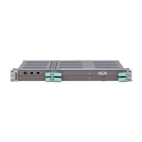
Figure 57 MMU2 E and F 155. Note: MMU2 F 155 has XPIC support.
4.2.2 Functional Block
This section describes the internal and external functions of the MMU, based
on the block diagram in Figure 58 on page 63.
6637
Radio Frame
Multiplexer
Modulator
Cable
Interface
Demodulator
Radio Frame
Demultiplexer
SPI
TDM
Multiplexer/
Demultiplexer
TDM Bus
PCI Bus
SPI Bus
HCC
HCC
RCC
RAU
Power
Power Bus
Secondary
voltages
DCC
Traffic
DCC
Traffic
BPI Bus (1+1) BPI Bus (1+1)
Control and
Supervision
Figure 58 B
lock diagram for MMU2
63
4/1555-CSH 109 32/1-V1 Uen B 2007-09-14

Related product manuals